
The concept of "earth"
Ⅰ、Definition
The equipotential point or plane serving as the reference for a circuit or system
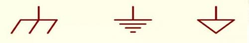
Ⅱ、符号
Ⅲ、Function
The grounding functions of different types vary
Ⅳ、Thoughts on "the Earth
●The ideal ground wire should be a physical entity with zero potential and zero impedance
●In actual wiring, the ground wire is on the PCB and has its own impedance component as well as reactance components composed of distributed capacitance and inductance. According to Ohm's Law, a voltage drop occurs when current passes through
●The ground wire forms a circuit with the source (power supply, signal source). The electric field in this circuit will induce RF current from the external electromagnetic field, which is commonly known as "noise", thereby causing EMI problems
The classification of ground in switching power supplies
● Place of Exchange
● Direct current ground
● Simulated ground
● Digital Land
●"Hot land"
● Cold ground
● Power ground
● Signal ground
● Safe
● Shielding ground
● Systematically
● Floating ground
Ⅰ、Exchange Venue
The neutral wire of alternating current, this kind of ground is usually a noise-generating ground and should be distinguished from the ground
Ⅱ、Direct current ground
The "ground" of a DC circuit, the zero potential reference point
Ⅲ、Simulation site
It is the zero potential of various analog signals
Ⅳ、Digital land
Also known as logical ground, it is the zero potential of various switch (digital) signals in digital circuits
Ⅴ、Hot land
It refers to the primary ground of a transformer that is not isolated from the power grid and is energized
Ⅵ、Cold ground
It refers to the secondary ground of the transformer, which is isolated from the power grid and not electrified
Ⅶ、Power ground
Zero potential reference points for high-current network devices, power electronics and magnetic devices
Ⅷ、Signal ground
It generally refers to the ground wire for sensing changing signals
Ⅸ、Signal ground
A circuit that provides a ground grounding point can prevent the risk of electric shock
Ⅹ、Shielding ground
Provide 0V reference or electromagnetic shielding for interconnected cables and main racks to prevent electrostatic induction and magnetic field induction
Ⅺ、Systematically
The common reference point for both analog and digital signals of the entire system
Ⅻ、Floating ground
Take a certain branch in the circuit as a 0V reference without grounding
The way of grounding
● Single-point grounding
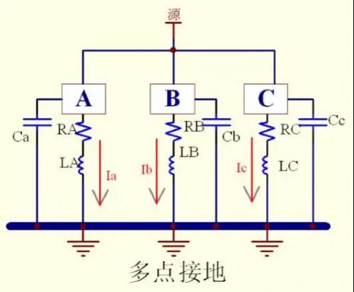
● Multi-point grounding
● Hybrid grounding
● Principles for selecting grounding
Ⅰ、Single-point grounding
● It means that the ground wires of all circuits are connected to the same point of the common ground wire to reduce mutual interference between ground circuits.
● It can prevent the current and RF current in different subsystems from traveling through the same return path, thereby avoiding common-mode noise coupling between them.
● According to the characteristics of different systems, series single-point grounding and parallel single-point grounding can be selected.
A. Single-point series grounding: It refers to the situation where the ground of all devices is connected to the ground bus, and then connected to the ground junction point through the bus

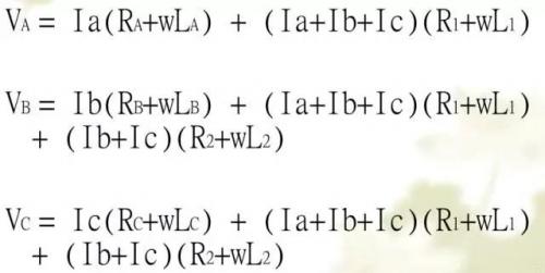
●There exists mutual common impedance interference:
●Advantages
The impedance of distributed transmission is extremely small
The wiring is simple and aesthetically pleasing
●Disadvantage:
Not suitable for high-frequency circuits (f≥1MHz)
It is not suitable for multiple power loop circuits
There exists common impedance interference among the subsystems
Due to the influence of the distributed capacitance to ground, a parallel resonance phenomenon will occur, which greatly increases the impedance of the ground wire
B. Single-point parallel grounding: It refers to the direct connection of the ground of all devices to the ground junction point, without sharing the ground bus

●Advantages
It can prevent common impedance interference among various modules within the system
●Disadvantage
Not suitable for high-frequency circuits (f≥1MHz)
It will be affected by parallel resonance
Due to the relatively long ground wires of each, the ground loop impedances are different, which will intensify the influence of ground noise and cause RF problems
Ⅱ、Multi-point grounding
It refers to the grounding of each part of the circuit within the system nearby
●Advantages
Parallel connection of multiple wires can reduce the total inductance of the grounding conductor
It can provide a relatively low grounding impedance
●Disadvantage
The length of each ground wire is less than 1/20 of the signal wavelength
Multi-point grounding may cause the formation of many grounding loops inside the equipment, thereby reducing the equipment's resistance to external electromagnetic fields
When different modules and devices are networked, the ground loop is prone to EMI problems
Ⅲ、Mixed grounding
●It combines the comprehensive application of single-point grounding and multi-point grounding. Generally, on the basis of single-point grounding, some inductors or capacitors are used for multi-point grounding. It takes advantage of the characteristic that inductors and capacitors have different impedances at different frequencies, so that the ground wire system has different grounding structures at different frequencies. It is mainly suitable for circuit systems operating at mixed frequencies.
●It is important to clearly distinguish the ground of analog circuits from that of digital circuits, as well as their optimal common connection points
Ⅳ、General selection principles for grounding
●Taking the highest frequency (corresponding wavelength λ) as the consideration object, if the length L of the transmission line is greater than λ, it is regarded as a high-frequency circuit; otherwise, it is regarded as a low-frequency circuit.
(1) For low-frequency circuits (<1 MHZ), it is recommended to use single-point grounding.
(2) For high-frequency circuits (>10MHz), it is recommended to use multi-point grounding.
(3) For high and low frequency hybrid circuits, hybrid grounding is adopted.
Considerations regarding "ground" in the actual wiring process of switching power supplies
General Provisions:
According to the actual application, first distinguish the types of ground wires, and then select different grounding methods
No matter what grounding method is used, the principle of "low resistance and low noise" must be followed
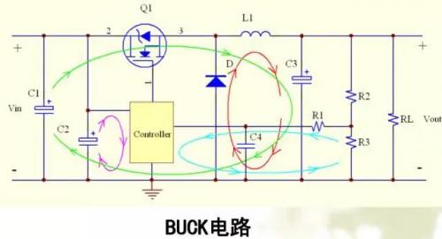
Basic circuit topology loop


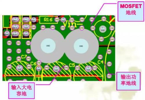
Power ground wire:
Due to the large current flowing through the power ground wire, if it is not handled properly, it will cause significant interference, cannot carry heavy loads, and may even fail to work normally.
Failure cases:
The BUCK line, due to the use of a large area of ground laying, causes excessive interference and is unable to carry heavy loads.

Success Story:
1.2KW BOOST circuit
Issues to note in Layout
● Different power ground wires need to be routed separately
● Try not to run the wires in parallel
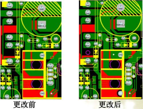
● Minimize the loop area as much as possible
● The principle of "short, thick and straight" must be followed. Due to the relatively large di/dt of the power ground wire, the antenna effect of overly long lines is obvious. A wire that is too thin will cause a significant voltage drop. Lines that are bent too much or at 90 degrees will produce a reflection effect
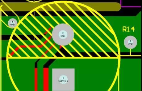
Drive ground wire

The ground wire of the drive source should be as close as possible to the driven device to form a minimum loop and reduce oscillation and EMI issues.
The grounding point of the Y capacitor:
● The concept of "source"
● "Quiet ground" is the lower end of the source
● The connection point of the Y capacitor emphasizes "quietness". It is obvious that the best connection point of the Y capacitor in the above figure is the negative terminal of C1 and the secondary pin 7 of the transformer T1.
Radiator grounding:

When the heat sink is at ground potential and the active device is at RF potential, the heat sink can be equivalent to a large common-mode decoupling capacitor when in operation, connecting RF current to ground.
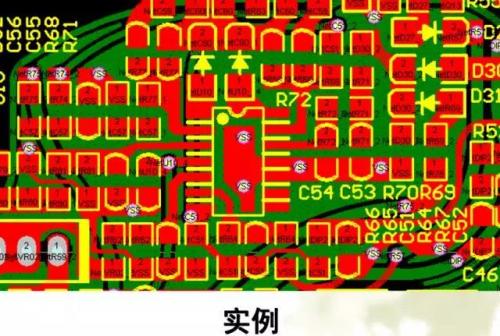
Application of local grounding surfaces

A local ground can capture the RF magnetic flux generated inside the device and the oscillator, which is most common in high-frequency circuits.
Summary
It is necessary to clarify the concept and classification of "earth"
Choose different grounding methods according to the type of base
The actual wiring should comply with the requirements of safety regulations and EMC
The key is to understand the role of "ground" in the power supply and weigh the pros and cons when wiring
免责声明: 本文章转自其它平台,并不代表本站观点及立场。若有侵权或异议,请联系我们删除。谢谢! Disclaimer: This article is reproduced from other platforms and does not represent the views or positions of this website. If there is any infringement or objection, please contact us to delete it. thank you! |

WeChat Official Account

WeChat Service
 Email
Email QQ
QQ 13823761625
