
Brushless motors are widely used in modern automated industrial fields due to their advantages such as high efficiency, low noise and long service life. The common control methods for brushless motors include non-inductive control, inductive control, field vector control (FOC), sine wave control, direct torque control (DTC), and model predictive control (MPC). These several control strategies are applied in different scenarios, and the difficulty of their implementation is also quite obvious. This article mainly discusses the three control methods I am familiar with - imperceptible, perceptible and FOC.
1 "Seamless control"
In the absence of rotor position sensors (Hall sensors), brushless motors are controlled to start and operate stably through corresponding algorithms and control strategies. Specific algorithms generally employ observed back electromotive force or other non-direct position sensors.
Zero-crossing detection, a common strategy for non-inductive control, is to determine the rotor position of a brushless motor by detecting changes in the back electromotive force. As shown in the figure, it is the back electromotive force detection circuit for non-inductive control.
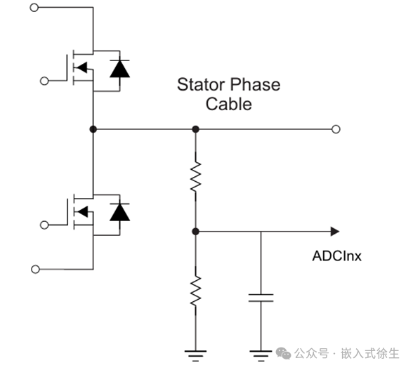
In the commutation principle of brushless motors, when any two of the brushless motors are electrified, the remaining suspended phase can detect the counter electromotive force. During the period when the rotor rotates from 0° to 60°, the counter electromotive force crosses zero once. This operation is commonly known as zero-crossing detection.
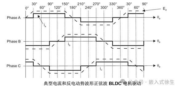
When any two phases of the brushless motor are energized, the remaining suspended phase can detect the counter electromotive force. When the counter electromotive force is detected at the zero position, the rotor is in the same direction as the suspended phase (parallel direction), that is, after phase commutation, it moves 30°, and then moves another 30° Angle, which is the commutation point. Therefore, by using six zero-crossing events to control the brushless motor, in order to achieve precise commutation points, the time delay of the 30° delay Angle in this cycle is calculated based on the time of the previous commutation cycle.
The start-up of contactless control is divided into three stages: pre-positioning, start-up acceleration, and closed-loop control.
1) First, power on two of them for a period of time to allow the rotor to rotate to the predetermined position. The duty cycle (generally 30 to 50) and the duration of power-on should not be too large, as this may cause overheating. The power-on time and duty cycle need to be determined based on different motor and load conditions. Otherwise, it may burn out due to prolonged power-on on a coil, or the time may be too short to be preset.
When starting the acceleration, power off (phase change) each connection in sequence according to the direction to be rotated. The startup process requires multiple phase changes and gradual acceleration. Just like the preset position, this acceleration process is also related to the specific motor and load. The size of the output duty cycle needs to be determined in combination with actual tests. If the commutation frequency is too low, the motor will accelerate slowly, shake and reverse, and the coil will also heat up severely. If the commutation frequency is too high, the motor is prone to losing step during operation, resulting in acceleration failure.
3) Closed-loop control: When the start-up acceleration reaches a certain speed and the back electromotive force and its zero-crossing point can be stably detected, the closed-loop control state can be switched.
2. Sensory control
Inductive control of brushless motors refers to the use of three switch-type Hall sensors in brushless motors (BLDC) to detect the rotor position. The on-off of MOSFETs is controlled based on the encoded outputs of the three Hall sensors, thereby achieving commutation.
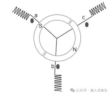
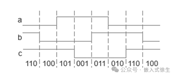
In a brushless motor, three Hall sensors are generally installed in a circular distribution at 120° intervals, as shown in the figure. The high and low levels of the output signal each occupy an Angle of 180°. Let the high level of the output be 1 and the low level be represented by 0. Then, the three output signals are represented by binary encoding as shown in the above table.
Each rotation of the rotor can output six signals, which exactly correspond to the six processes of the six-step square wave commutation. We can control the on and off of the MOSFET in the order provided by the factory truth table
3 Magnetic Field Directional Control (FOC
FOC (Field-Oriented Control), which literally means field-oriented Control and is also known as Vector control (VC, Vector Control), is currently one of the best methods for efficient control of brushless DC motors (BLDC) and permanent magnet synchronous motors (PMSM). FOC aims to precisely control the magnitude and direction of the magnetic field, ensuring smooth motor motion torque, low noise, high efficiency, and high-speed dynamic response.
The stator magnetic field is fixed, while the rotor magnetic field moves as the rotor rotates. When the Angle between these two magnetic fields is 90 °, the conductors in the rotor cut the magnetic field lines of the stator magnetic field at the fastest speed, which leads to the generation of the largest induced current in the rotor conductors. The Lorentz force that these induced currents experience in the stator magnetic field is also the greatest, and thus the rotational torque (i.e., electromagnetic torque) generated is also the largest. So, how to keep the stator magnetic field and the rotor magnetic field always at a 90° difference to ensure that the motor always generates the maximum torque is the problem solved by FOC vector control.
FOC control process
The FOC control process of brushless motors is carried out by performing Clarke transformation on the three-phase current sampling of the brushless motor to convert the three-phase sinusoidal current signal into a two-phase sinusoidal signal. Then, through Park transformation (rotational transformation), it is transformed into two DC signals as the input of the current closed loop. Finally, through reverse Park transformation and space vector pulse width modulation, the on-off of the three-phase full bridge is controlled. Thus, the control of brushless motors is achieved.
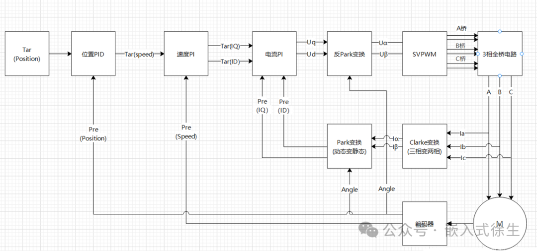
The explanation of the above picture is as follows:
(1) Sampling the three-phase current of the motor to obtain Ia Ib Ic
(2) Obtain Ia Ib Ic through Clark transformation
(3) The Iq Id will be obtained through the Park transformation
(4) Calculate the Iq Id and the set value Iq_ref Id_ref error
(5) The above-mentioned errors are taken as the pid controller to obtain the output control voltages Uq and Ud
(6) Perform the inverse park transformation on Uq and Ud
(7) The output is sent to the MOSFET through the svpwm module (clark reverse transformation), generating orthogonal magnetic fields between the stator and rotor to control the motor operation.
免责声明: 本文章转自其它平台,并不代表本站观点及立场。若有侵权或异议,请联系我们删除。谢谢! Disclaimer: This article is reproduced from other platforms and does not represent the views or positions of this website. If there is any infringement or objection, please contact us to delete it. thank you! |

WeChat Official Account

WeChat Service
 Email
Email QQ
QQ 13823761625
