
Preface
Music has become an indispensable part of people's lives, and people's demands for sound quality are also getting higher and higher. When playing digital albums with portable speakers, one may find that the music effect presented is not satisfactory. This is due to the mismatch between the selected audio amplifier and speakers and the audio source. Audio power amplifier, also known as audio power amplifier. It can amplify the small signals output by the audio source through a complex circuit structure composed of power transistors and operational amplifiers and then output them, causing the external speaker to vibrate and produce sound. Only by choosing a suitable audio power amplifier chip can the original state of the sound be restored to the greatest extent. The main performance indicators of audio power amplifiers include: signal-to-noise ratio, distortion, output power, frequency response, conversion rate, etc.
I丶Signal-to-noise ratio
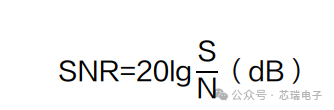
The noise is the inherent noise of the audio power amplifier, mainly generated by power transistors (such as vacuum tubes and transistors), integrated circuits and their parasitic parameters, etc. The Ratio of the output Signal voltage to the voltage of the Noise signal output simultaneously is the signal-to-noise ratio (SNR). The greater the signal-to-noise ratio, the smaller the noise mixed in the signal, and the higher the quality of the audio power amplifier. According to the high-fidelity requirements, the signal-to-noise ratio should reach above 90dB. The formula for calculating the signal-to-noise ratio is as follows
A-weighted is A standard weight curve used for audio measurement, which is applied to simulate the response characteristics of the human ear to A 40-square pure tone (40dB SPL). The sound pressure level is derived from A-weighted, denoted as dBA, or referred to as A-weighted dB level. A-weighting is A widely adopted single-value evaluation index for noise and can be measured by a sound level meter. The signal-to-noise ratio is the prerequisite for dynamic range. Dynamic range is the ratio of the maximum signal to the minimum signal. If the signal is smaller than the noise, then no matter how small the signal is, it is meaningless. Therefore, dynamic range can be regarded as the ratio of the maximum signal to the noise. So, in a certain sense, the signal-to-noise ratio can be regarded as the dynamic range of an audio power amplifier.
II丶Degree of distortion
Distortion refers to the difference between the processed sound and the original sound. The smaller the distortion, the better the sound quality.
Harmonic distortion refers to the additional harmonic components in the output signal compared to the input signal. It is caused by the fact that the working state of the power amplifier is not completely linear.
Total Harmonic Distortion (THD) refers to the sum of all harmonic components present in a signal relative to the fundamental wave. The calculation formula for total harmonic distortion is as follows:
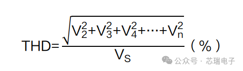
Among them: VS is the input signal; V2 is the second harmonic signal; Vn represents the NTH harmonic signal.
Total Harmonic Distortion+Noise (THD+N, Total Harmonic Distortion+Noise), in addition to focusing on harmonic distortion, also pays attention to noise, which is the influence of all harmonics and noise under the specified bandwidth. The calculation formula for total harmonic distortion plus noise is as follows:
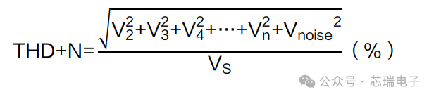
Among them: Vnoise is a noise signal.
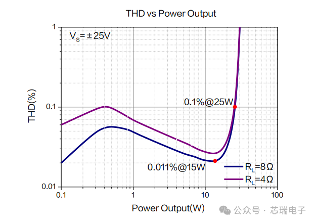
The nominal total harmonic distortion (THD) of an audio operational amplifier is generally 1% to 0.01%. Different input signals, different closed-loop gains, different output powers, and different speaker loads will affect the test value of total harmonic distortion. Usually, relevant conditions are also indicated, for example: THD=0.011%@15W 8Ω (when the output power is 15W and the load is 8Ω, THD is 0.011%). The relationship curve between distortion and output power is shown in Figure 1. When the output power is between 1 and 25W, the distortion is relatively low. When the output power exceeds 25W, it has reached the output limit, and the distortion increases sharply, resulting in signal clipping distortion.
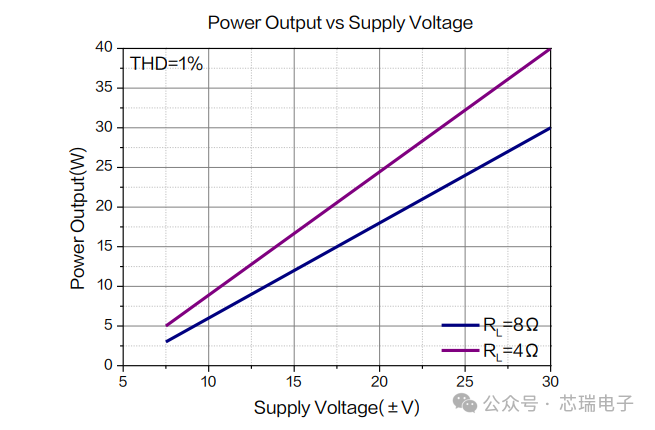
Output power refers to the output capacity of an audio power amplifier on a load under specified voltage conditions when a certain degree of distortion is met. Output power affects the amplitude of an audio signal, which is reflected subjectively as the volume of the sound.
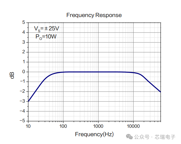
The frequency range that the human ear can hear is approximately 20Hz to 20kHz. That is to say, as long as the audio power amplifier can respond to signals within this range, it is fine. The frequency of an audio signal is related to the pitch we subjectively perceive. The higher the frequency, the higher the pitch, that is, the sharper the sound. The lower the frequency, the lower the pitch, that is, the voice is relatively deep.
Frequency response refers to the amplification performance of an audio power amplifier for different frequencies. In essence, it measures whether the amplification factors for high-frequency, mid-frequency, and low-frequency signals are uniform. The ideal frequency characteristic curve should be straight. However, generally speaking, the amplification factor of audio power amplifiers for high-frequency and low-frequency band signals will be somewhat attenuated. If the attenuation is excessive, it will affect the fidelity of the signal in that frequency band. The variation range from 20Hz to 20kHz is within 3dB, as shown in Figure 3.
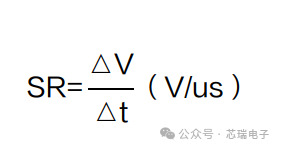
The Slew rate (SR) refers to the maximum variation speed of the output signal of a closed-loop amplifier when the input is a step signal, also known as the slew rate. Since the output signal after the operational amplifier is a signal waveform with a "certain slope", the time required for the signal to rise by 10% to 90% is expressed as the rising edge time △t of the signal, and the corresponding signal rise amplitude is △V. The formula for calculating the pendulum rate is as follows:
The conversion rate of an audio power amplifier has a significant impact on the quality and performance of its treble. The faster the conversion rate, the more accurate the captured high-frequency signal.
It should be noted that to avoid severe distortion of the sinusoidal signal, there must be certain limitations on the frequency of the signal and the amplitude of the output signal to ensure that the maximum slope of the output signal does not exceed the slew rate of the operational amplifier; otherwise, the output signal will be distorted, similar to a triangular wave.
Summary
To maximize the amplification of sound while ensuring the quality of the audio source, it is necessary to select an appropriate audio power amplifier chip to match the audio source with the speaker. Generally speaking, the higher the signal-to-noise ratio, the lower the distortion, the greater the output power, the better the frequency response characteristics, and the higher the conversion rate of the audio power amplifier chip, the better its performance.
免责声明: 本文章转自其它平台,并不代表本站观点及立场。若有侵权或异议,请联系我们删除。谢谢! Disclaimer: This article is reproduced from other platforms and does not represent the views or positions of this website. If there is any infringement or objection, please contact us to delete it. thank you! |

WeChat Official Account

WeChat Service
 Email
Email QQ
QQ 13823761625
