
Portable battery-powered electronic devices (such as mobile phones, laptops, wireless speakers, power tools, etc.) are driving the continuous growth of the USB power transfer (PD) market. USB PD brings huge advantages to consumer electronics. They can provide up to 240 W of power through the same USB Type-C connector (refer to the USB PD 3.1 version specification). Figure 1 shows a mobile phone charged through the USB Type-C connector.

Some solutions require multiple integrated circuits (ics), including port detectors, microcontrollers and chargers for power transmission. Although these solutions can be used, they will occupy on-board space, increase the cost of the solutions, and require custom firmware, which is very time-consuming to produce.
An independent PD controller can help address these challenges. It can manage power issues without the need to develop firmware.
USB-C PD power supply requirements
USB PD has a significant advantage: Consumers can charge a 2.5W mobile phone and a 25W cordless drill using the same cable and power adapter. The days when drawers were stuffed with all kinds of different cables or the correct charger could never be found have become a thing of the past.
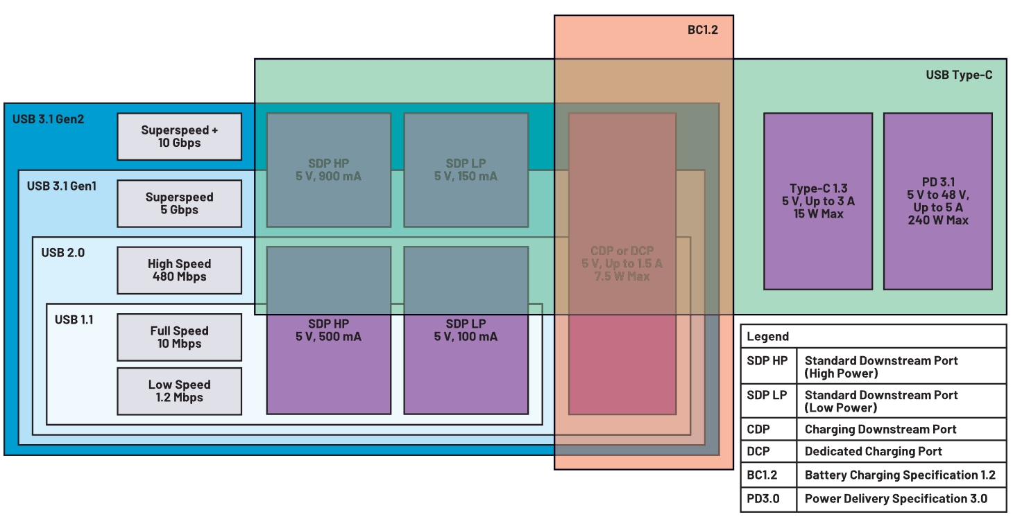
Before understanding USB PD, we must review previous USB standards to understand the advantages and challenges that USB PD possesses. The original USB standards - USB 1.1 and USB 2.0 - were used for data transmission rather than power transmission. They only allow USB cables to transmit a maximum voltage of 5 V and a current of 500 mA.
As time went by, consumers began to demand that USB offer more functions. They wanted to charge the battery quickly via a USB cable. At this point, the maximum current of 500 mA could no longer meet the requirements. The BC1.2 standard allows for the transmission of up to 7.5W of power via USB cables - 5V voltage and 1.5A current. This standard meets the demands of these consumers. The BC1.2 standard has expanded the ability to charge batteries via USB cables. After the BC1.2 standard, each new standard has increased the power capacity on the basis of the previous one. Type-C 1.3 expands the power capacity to 15 W (maximum value), while USB PD 3.0 upgrades the system power to 100 W (maximum value). Its latest specification update, USB PD3.1, further expands the power capacity to 240 W (maximum).
BC1.2 and Type-C 1.3 continue to provide the 5 V power rail previously used in all USB standards, but increase the power capacity to 7.5 W and 15 W respectively by increasing the maximum current to 1.5 A and 3 A. USB PD3.0 also increases the current and voltage capacity, enabling the power capacity to reach 100 W (maximum value). It allows two devices to transfer up to 20 V voltage and 5 A current via a USB cable. The new PD3.1 specification supports up to 48 V voltage and 5 A current.
Figure 2 summarizes and lists the power capacity, maximum current and voltage allowed by each USB standard.
The USB PD 3.0 standard requires that the power supply provide a specific power rail according to its power capacity. A power supply capable of providing more than 15 watts must provide 5 V and 9 V power rails. A power supply capable of providing more than 27 watts must offer 5 V, 9 V and 15 V power rails. Finally, a power supply capable of providing more than 45 W must offer power rails of 5 V, 9 V, 15 V and 20 V.
The power supply also provides different current outputs on these power rails. The power supply provides A current between 500 mA and 3 A on the 5 V power rail. The power supply provides A current between 1.67A and 3 A on the 9 V power rail. The power supply provides a current between 1.8A and 3A on the 15 V power rail. Finally, the power supply provides A current between 2.25 A and 5 A on the 20 V power rail (Figure 3).
The USB PD 3.1 standard adds three additional power supply rails to the power supply. The power supplies providing 28 V, 36 V and 48 V fixed power rails respectively support power levels up to 140 W, 180 W and 240 W. The power supply must provide up to 5 A of current for these power rails.

The PPS function is very useful. It can accelerate the charging speed of lithium-ion batteries by optimizing the operating point of the switch charger. During the constant current stage of the charging cycle, the charger provides a fixed current to the battery, and the battery voltage will gradually increase until it eventually reaches the charging cut-off voltage. Under normal circumstances, the input of a charger is fixed. When the input of the charger is much greater than the battery voltage, power loss will occur. The PPS function adjusts the input voltage of the charger to make its working efficiency as close as possible to the peak efficiency. This move reduces power consumption. When the charging current increases, the charging speed of the battery accelerates.
PPS can achieve countless combinations of voltage and current through USB cables. Designers who want to use the PPS function must find a way to make the power supply and online devices agree on the amount of power that the power supply should provide.
USB-C PD design module
Starting to charge in a discrete USB PD system is not a simple task. The power supply (such as a wall adapter) is connected to the online device (such as a mobile phone or an electric drill) via a USB cable. Both of these devices usually require the use of multiple ics to achieve back-and-forth communication in order to supply power to the online devices (Figure 4).
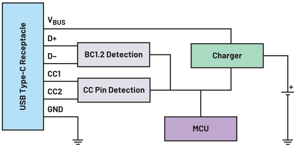
The BC1.2 detection IC supports traditional USB adapters. Although newer devices adopt USB Type-C more widely, many applications still use the old USB specifications. The BC1.2 compatible port uses the D+/D- pin to transfer the power capacity of the power supply instead of the CC pin. The BC1.2 detection IC reads the D+/D- pins to charge applications that still use the traditional USB standard.
This charger IC charges the batteries of online devices safely and effectively. The power supply will provide a constant voltage for the input sources of online devices and chargers. Then the charger ensures that the battery charging capacity has reached the charging voltage, current and temperature specifications.
Finally, the microcontroller unit (MCU) module organizes the communication among other ics. The MCU communicates with the CC pin detection IC to determine the power capacity of the power supply. Then, the MCU compares the capacity of the power supply with the power requirements of the charger and battery to determine how much current and voltage the power supply should provide. The MCU feeds back the final power setting to the CC pin detection IC to correctly configure the power supply. Once the correct current and voltage are confirmed, the MCU will configure and enable the charger.
The number of components required by USB PD exceeds that provided by traditional USB or standard Type-C designs. More ics lead to higher costs and larger solution sizes. It also requires a complex firmware design to manage the communication between different components and meet all the requirements of the USB PD 3.0 standard. Just the firmware design alone may prolong the development cycle, unless the designers are familiar with the USB specifications.
Independent PD controller
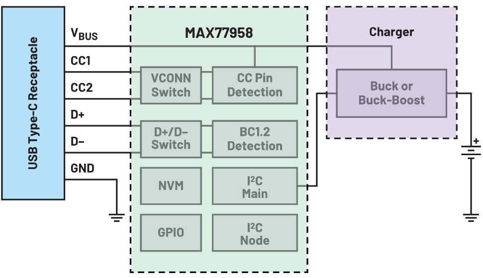
By integrating CC pin detection, BC1.2 detection and MCU into one IC, the standalone PD controller can help simplify the USB PD design. The four-IC design has now been transformed into a dual-IC design, saving circuit board space and costs.
The embedded MCU integrates all USB PD 3.0 standard communication protocols and timing requirements and is the most powerful part in the standalone PD controller. Designers no longer need to spend time on development to keep up with these specifications.
An example of an independent PD controller is the MAX77958 (Figure 5). The MAX77958 features two unique functions: non-volatile memory and direct control of the I2C main port of the accompanying charger. These two functions eliminate the need for an external MCU and there is no need to develop custom firmware.
Custom scripts are written in the GUI using simple and easy-to-use commands. The software converts the custom script into hexadecimal format and writes it into the IC configuration area. Developers can define simple functions and sequences based on the functions provided by their applications.
Figure 6 shows some custom script programming functions that designers can use. The GUI outputs binary (bin) and hexadecimal (hex) files based on custom scripts. Customized scripts are a unique feature that helps significantly shorten the development time.

Conclusion
The USB PD specification has greatly increased the number of battery-powered devices charged via USB cables. This specification Outlines seven new power rail requirements - 5 V, 9 V, 15 V, 20 V, 28 V, 36 V and 48 V - to help accommodate a wide range of power capacities. Before starting charging, the power supply and online devices need to determine the current and voltage levels.
The standalone PD controller integrates most modules into one IC, which helps simplify the design process. Some do not even require the use of external MCUS and custom firmware. The standalone PD controller helps accelerate your design and development, ensuring you always stay ahead of the new trends in USB PD.
| Disclaimer: This article is reproduced from other platforms and does not represent the views or positions of this website. If there is any infringement or objection, please contact us to delete it. thank you! 矽源特科技ChipSourceTek |

WeChat Official Account

WeChat Service
 Email
Email QQ
QQ 13823761625
