
At present, most battery management systems (BMS) incorporate passive balancing functions that can regularly adjust all series-connected battery cells to a common SOC value. Passive balancing achieves this by connecting a resistor to each battery cell as needed to dissipate energy and reduce the SOC of the battery cell.
As an alternative to passive balancing, active balancing uses power conversion to redistribute charges among the individual batteries in the battery pack. This can achieve a higher balancing current, lower heat generation, faster balancing time, higher energy efficiency and longer operating distance.
This article introduces some common active balancing methods and explains the working principles of these methods.
Battery balance
Even if the initial matching is good, the batteries in the battery pack will undergo capacity changes over time. For instance, batteries at different physical locations in a battery pack may experience varying temperatures or pressures, thereby affecting their capacity. Furthermore, minor manufacturing differences may magnify over time and cause capacity variations. Understanding capacity differences is crucial for identifying the sources of SOC imbalance.
The variation of the SOC of the battery cell is mainly determined by the battery capacity and the current entering and leaving the battery. For example, when A 4-Ahr battery receives a current of 1 A within 1 hour, the SOC change is 25%, while a similar 2-Ahr battery will experience a 50% SOC change.
Maintaining SOC balance requires adjusting the charging/discharging current of each battery according to its capacity. The batteries connected in parallel will automatically perform this operation because the current will flow from the high SOC battery to the low SOC battery. In contrast, the current between series-connected batteries is the same. If there is a capacity difference, an imbalance will occur. This is very important because most battery packs have series battery connections, even though they also include parallel connections.
SOC adjustment is applicable to both passive balancing and active balancing.
Passive balancing reduces the battery SOC by placing resistive loads (commonly BJT or MOSFET transistors) on each battery. However, active balancing uses the switching mode method to redistribute energy among the batteries in the battery pack.
Due to the increased complexity and cost during the implementation process, active balancing has traditionally been limited to battery systems with higher power levels and/or large-capacity batteries, such as batteries in power stations, commercial energy storage systems (ESS), home energy storage systems, and battery backup devices. Now there are new solutions with significantly reduced costs and complexity, enabling an increasing number of applications to take advantage of the benefits of active balancing.
The current of passive balancing is usually limited to 0.25 A, while active balancing can support up to 6 A. A higher balancing current enables faster balancing, thereby supporting larger-capacity battery cells, such as those used in ESS. In addition, a higher balancing current supports systems that operate at fast cycles, in which balancing must be completed quickly.
Passive balance will only consume energy. Active balancing, on the other hand, redistributes energy, thereby significantly enhancing energy efficiency. Passive balancing is only practical during the charging cycle because operations during discharge will accelerate the energy consumption of the battery pack. On the contrary, active balancing can be implemented during charging or discharging.
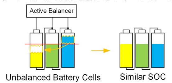
The ability to actively balance during discharge can provide more balancing time and allow charges to transfer from strong batteries to weak batteries, thereby extending the operating time of the battery pack (Figure 2). In conclusion, active balancing is beneficial for applications that require faster balancing, limited heat load, improved energy efficiency, and increased system operating time.
Common active balancing topologies include those based on direct transformers, switch matrix plus transformer, and bidirectional step-down - step-up balancing.
Transformer-based (bidirectional flyback type) active balancer
The bidirectional flyback converter allows for bidirectional charge transfer. The bidirectional flyback converter is designed as a boundary mode flyback converter. Each battery cell in the battery pack requires a bidirectional flyback converter, including a flyback transformer (Figure 3).
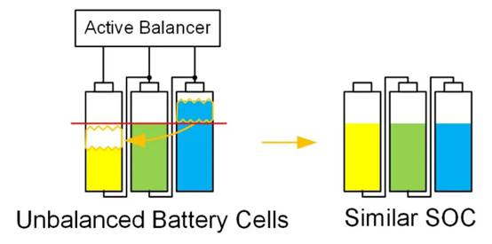
Figure 3 shows that the transformer-based bidirectional active balancer can transfer charges in both directions and can use a 24V power rail. Source: Monolithic Power Systems
When using different transformer designs, there are several possible energy transmission paths. For example, energy can be transferred from one battery to a group of batteries within a battery pack. Energy can be transferred from any battery to the top of the battery pack (connected to the battery pack terminals), which requires a large high-voltage flyback transformer. Energy can also be transferred to or from the auxiliary power rail, such as the 24 V system shown in Figure 3.When using the transformer-based active balancing method, many transformers are usually required, which leads to a large volume and high cost for the solution of high-series-number battery packs.
Switch matrix plus transformer active balancer
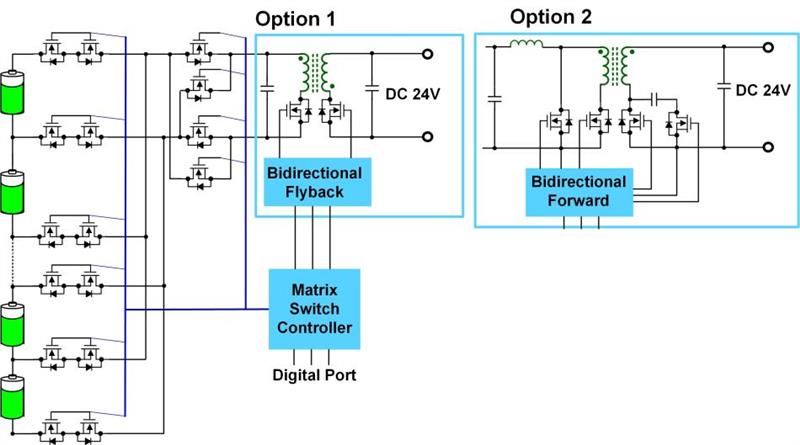
The switch matrix plus transformer method uses a switch array to connect transformers to each battery cell, thereby reducing the number of transformers to one. In the switch matrix, there are two types of switches: battery cell switches and polarity switches.
The battery switch is a back-to-back MOSFET directly connected to the battery cell. They can prevent the current flowing in the direction of charging and discharging. On the contrary, polar switches only block current flowing in one direction and they are directly connected to the secondary side of a single bidirectional flyback converter or a bidirectional forward converter (Figure 4).
Bidirectional pressure-reducing - pressure-increasing active balancer
The step-down - boost active balancer adopts a simpler method and utilizes the commonly used step-down and boost battery charger technology. Voltage-boost active balancing does not move the charge to various positions in the battery pack or to individual power rails, but to directly adjacent batteries. This greatly simplifies the balancing circuit and utilizes the simultaneous operation of multiple balancers to distribute the charge throughout the battery pack.
The dual-channel step-down - boost balancer can provide bidirectional charge movement between two adjacent cells by operating in either the step-down balance mode or the boost balance mode. By placing a dual-channel step-boost balancer on each pair of batteries, the charge can move throughout the battery pack (Figure 5).
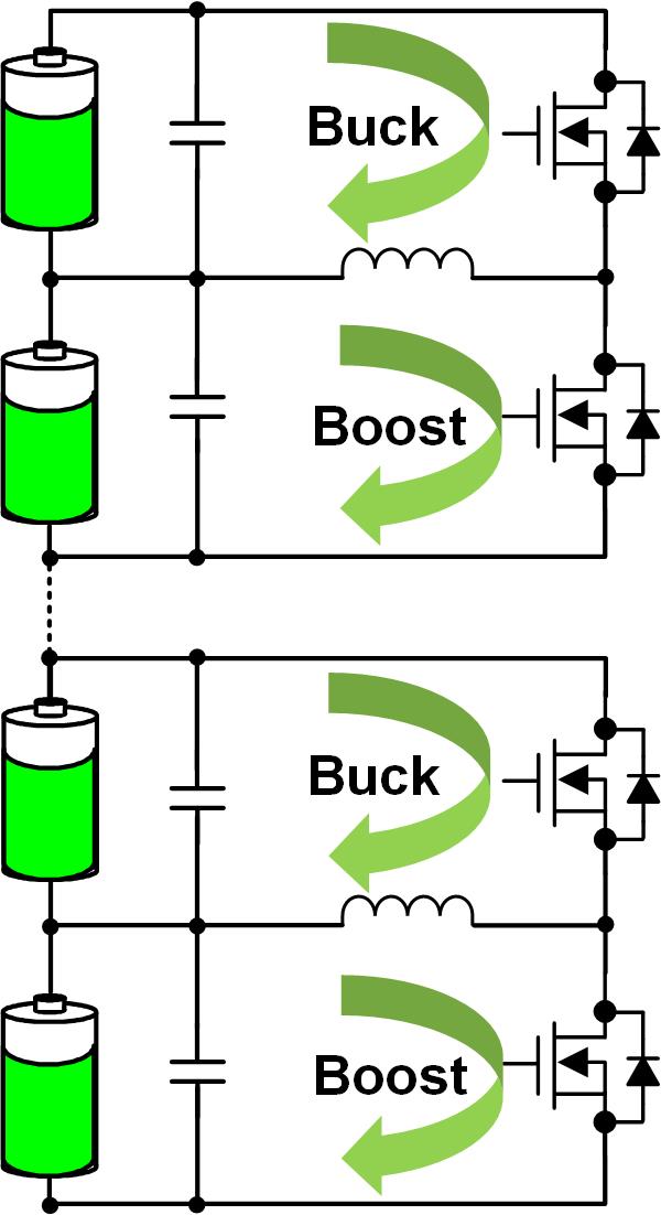
In the step-down balancing mode, the active balancer transfers energy from the upper battery (CU) to the lower battery (CL).
In the boost balance mode, the active balancer transfers energy from CL to CU.
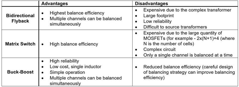
Among the three types of active balancers, the bidirectional reduction-boost active balancer is simple and reliable. Table 1 compares these three active balancing methods.
As the demand for safer, more energy-efficient and longer-lasting lithium-ion battery systems continues to grow, the need for better battery balance is also increasing day by day. Passive balance is limited to small currents that consume energy and is no longer sufficient to meet these requirements.
Therefore, active balancing solutions are increasingly adopted by more and more people due to their advantages of high current and fast battery balancing. In particular, the bidirectional step-down - boost active balancer offers simplicity and reliability.
免责声明: 本文章转自其它平台,并不代表本站观点及立场。若有侵权或异议,请联系我们删除。谢谢! Disclaimer: This article is reproduced from other platforms and does not represent the views or positions of this website. If there is any infringement or objection, please contact us to delete it. thank you! |

WeChat Official Account

WeChat Service
 Email
Email QQ
QQ 13823761625
