
The auto industry is changing. Tasks that can only be done by the internal combustion engine today will be handled by hybrid, electric and even fuel cell-powered vehicles in the future. In the past, many manufacturers focused on the mechanical components necessary for traditional internal combustion engines and transmission systems, but in the future, the focus will shift to other components. They may develop new solid-state batteries to increase range and charge and discharge times that are not possible with current lithium batteries, or they may focus on developing high-performance chargers, DC/DC converters, and motors.
As the core component, the Battery Management System (BMS) is responsible for the proper management and monitoring of the battery. Currently, electric cars use lithium-ion batteries. These cells are connected together to bring the battery pack to the required total voltage. The existing single battery voltage is about 3.6V to 3.7V, and the power battery 520 V or 900 V high voltage system requires about 140 to 250 batteries. In this configuration, the temperature, impedance (internal resistance of the battery), voltage, and charge and discharge current of the battery must be monitored.
BMS details
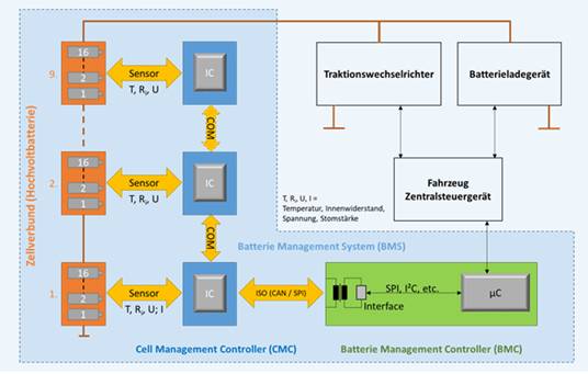
The BMS generally includes components such as a single battery management controller (CMC), main control central unit, or battery management controller (BMC). The CMC uses a multi-channel IC (currently configured with a maximum of 16 channels) to perform monitoring functions, and the BMC controls each CMC (Figure 1).
Monitor battery parameters (temperature, impedance, voltage and current)
Temperature monitoring
Typically, NTC thermistors are pressed against the cell or module wall, or electrically connected to measure its temperature. As the temperature of the thermistor rises, the resistance value decreases and the sensitivity increases (due to the large negative temperature coefficient of the resistance). The temperature can be determined using an on-chip integrated analog/digital converter (ADC) by measuring the voltage of the resistance-thermistor network.
An accurate temperature reading is extremely important for the proper functioning of the battery and the safety of the system. The NTC and the resistance of the measuring circuit are related to the accuracy of temperature measurement.
In Figure 2, the NTC can be an NTCS0603E3103FLT monolithic ceramic NTC surface mount thermistor (as shown in Figure 3), with an R25 value of 10 kW, ± 1%, and a B value of 3435 K, ± 1%. The mechanical bending strength of the device is superior to that of some competing multilayer devices mounted on a flexible PCB (FPC).
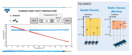
The thermistor also has a high thermal cycle tolerance and low resistance drift at high temperatures. NTC thermistors can be placed in the TNPW/TNPU series fixed resistance network - TNPW/TNPU series resistors have ultra-precise tolerances, with resistance thermal coefficient as low as ± 0.1%, ± 25 ppm/℃, Or in ACAS network resistors that support ± 0.05% relative tolerances and 0.1% absolute tolerances (Figure 4). The control chip samples the voltage generated by the NTC thermistor (Vntc) and detects the high and low thresholds.
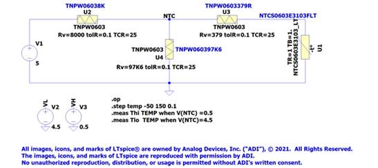
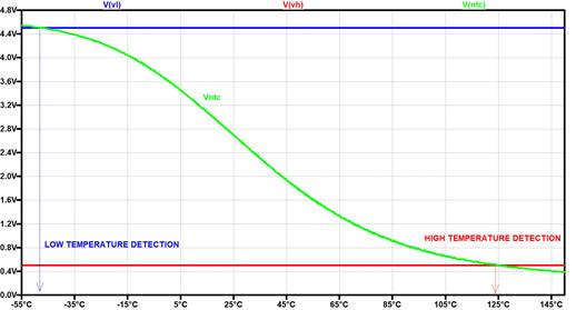
Figure 2 - Image source: LTspice XVII analog chip or ADC input resistor/thermistor partial bridge voltage for battery temperature detection
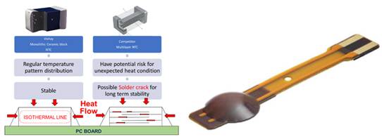
Figure 3 - NTC reference design, technical performance comparison and NTCAFLEX05 series flexible foil sensor reference design; Image credit: Vishay
Impedance monitoring
Full impedance measurement is not required. The advantage of this measurement method is that state of charge (SOC) and State of health (SOH) can be estimated more accurately. In simple terms, the method used for measurement is to apply alternating current of different frequencies. Then, like electric currents, complex voltages are transformed and resolved using a software-based model.
Battery voltage monitoring
Single cell voltage is generally measured using a chip integrated ADC. This method uses a multiplexer to measure the voltage of each cell in turn and convert it into an ADC digital signal. These digital signals are then evaluated.
Current monitoring
Current (charge or discharge current) is not measured on a cell-by-cell basis, but on a battery pack. The background of this measurement method is that the battery pack is "filled" by a central charger, which can be charged AC by an integrated charger (on-board charger, or OBC), or DC by an external charger. Since the batteries are in series, the current of all batteries is the same, so the system current only needs to be measured once. A Hall-effect current sensor or a low-resistance shunt resistor can be used for measurement.
Another core task of BMS is to balance each battery. During the production process, the capacity and internal resistance of each battery will vary due to different processing processes. As a result, the battery pack charges or discharges unevenly. In order to fully use the full energy (endurance) of the battery, it is necessary to balance the capacity and voltage of each battery. There are two basic principles of charge balance: active equilibrium and passive equilibrium.
Balance
In active equalization, excess battery energy is transferred to the coil through the circuit when the field effect transistor is turned on. When turned off, the energy in the coil is transferred to the next battery through the diode. This method continues until all batteries reach full charge voltage (Figure 5).
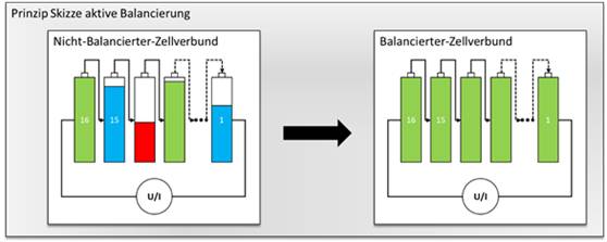
Figure 5 - Schematic diagram of active equalization; Image credit: Vishay
Passive equalization uses a drain resistor to convert excess battery energy into heat. The chip measures the voltage of each battery as it charges, and turns on the resistor when it reaches a threshold. This process can occur on one or more cells at the same time (Figure 6). The resistors used in this method are usually machined using thick film technology. They have high temperature coefficients and high initial tolerances. Vishay offers a significantly different approach. Compared with traditional thick film resistors, double-coated CRCW-HP resistors and specially trimmed RCS resistors can increase continuous power by two to three times in the same occupying area. In addition, in the case of the same power requirements, the use of these series of resistors can reduce the required printed circuit board space, while saving costs.
Another type that can produce the same effect is the RCL series resistors, which are wide terminal resistors for increased continuous power and better thermal cycling performance. The automotive industry requires reliable welding between components and printed circuit boards in the temperature range -55 °C to +125 °C and with increased cycling, which constitutes a
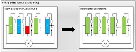
Figure 6 - Passive equilibrium diagram; Image credit: Vishay
Due to the high cost of the active equalization circuit and the narrow manufacturing tolerance of the internal resistance and capacitance of each battery, passive equalization is mainly used in the automotive field.
Functional Safety (ISO 26262, ASIL-D)
Batteries and their monitoring systems are critical to safety. Therefore, the components used by the system, as well as the entire system itself, must be developed according to ISO 26262 to meet the requirements of ASIL-D. Therefore, the BMS with voltage measurement, temperature measurement, current measurement (except internal resistance measurement) function is as important as the airbag system, braking system and power steering system. If these systems fail or are defective, it will directly endanger life and limb safety.
Redundant independent measurement methods minimize risk
In this case, monitoring the battery voltage is one of the key parameters, because each battery overcharge or deep discharge will cause an internal short circuit, resulting in thermal breakdown of the battery the next time it is charged.
Redundant battery voltage measurement can be performed using two battery chips. The disadvantage of this approach is that the same method is used for voltage measurement, and at the same time, the solution used is costly.
Another solution is to measure the battery voltage in an analog manner using a drain equalization resistor, comparing it to the battery voltage measurement results of the chip. This is a cost-effective independent measurement method. The above thick film leakage resistance is not suitable for this measurement. Instead, thin film resistors should be used because they guarantee accurate measurements throughout the service life cycle, even under harsh conditions of use.
Vishay also offers a variety of options for this purpose. The first is the MC-HP series resistors produced by special thin film technology. Its advantage is long-term stability (≤ 0.2%; P70, 1000 hours), twice the performance of standard thin film resistors. This is followed by the wide terminal MCW series resistors using thin film technology (external dimensions 0406 and 0612). The series meets long-term stability (≤ 0.2%; P70, 1000 hours), continuous power space ratio requirements, almost the same continuous power only one-third of the conventional space (Figure 7), improved thermal cycle performance (3000 cycles). With these characteristics, this series of resistors is suitable for use as leak resistors for BMS or battery voltage measurement resistors to meet the requirements of ASIL-D's future entire system.
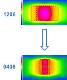
Figure 7 - High performance wide terminal film resistance thermal map comparison, the required space is one-third of conventional terminals; Image credit: Vishay
Figure 7 - High performance wide terminal film resistance thermal map comparison, the required space is one-third of conventional terminals; Image credit: Vishay
Author:

Adrian Michael is the Automotive Product Marketing Manager at Vishay. He holds a master's degree from the Westsachsische Hochschule Zwickau University of Applied Sciences, West Saxony, Germany, and worked at Axellon.
免责声明: 本文章转自其它平台,并不代表本站观点及立场。若有侵权或异议,请联系我们删除。谢谢! Disclaimer: This article is reproduced from other platforms and does not represent the views or positions of this website. If there is any infringement or objection, please contact us to delete it. thank you! |

WeChat Official Account

WeChat Service
 Email
Email QQ
QQ 13823761625
