
Triode has three working states: cut-off, amplification, saturation, amplification state is very learned and very complex, mostly used in integrated chips, such as OP-amp, now not discussed.
In fact, the amplification of the signal we usually use the operation amplifier processing, the transistor is more used as a switching tube, and only cut off, saturated two states.
The cut-off state is considered as off, and the saturated state is considered as on.
When Ib≥1mA, it is fully guaranteed that the triode works in a saturated state, and the Ic for a low-power triode at this time is tens to hundreds of mA, which is more than enough to drive power devices such as relays and buzzers.
Examples of triode circuits
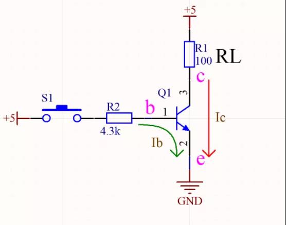
The triode arrow is understood as a switch, as shown in the following picture: NPN type triode, press the switch S1, about 1mA Ib flow arrow, the triode works in the saturated state, the c pole to e pole is completely on, the level of the c pole is close to 0V(GND), and the voltage drop at both ends of the load RL is close to 5V.
Ib and Ic currents flow into the e pole, depending on the direction of the current, e is extremely low, should be connected to the ground, c pole is connected to the load and power supply.
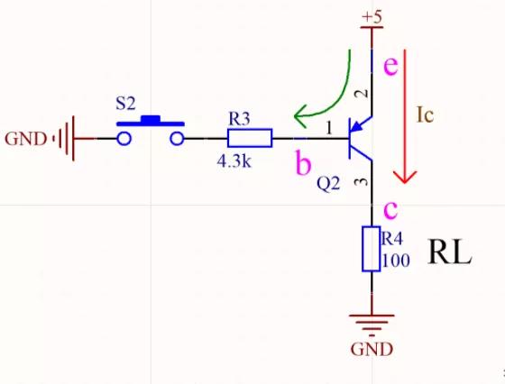
The following picture shows PNP triode, press the switch S2, about 1mA Ib flow arrow, the triode works in the saturated state, the e pole to the c pole is fully on, the level of the c pole is close to 5V, and the voltage drop at both ends of the load RL is close to 5V.
Ib and Ic current flow out of the e pole, according to the current direction, e is extremely high, should be connected to the power supply, c pole is connected to the load and ground.
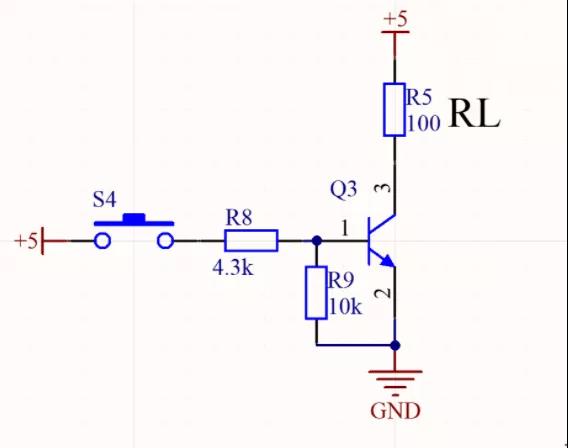
NPN triode as shown below, for NPN triode, a pull-down resistor should be added in the b pole, one is to ensure that the capacitor between b and e poles accelerates the discharge and speeds up the triode cutoff; The second is to ensure that the triode b pole is given a known logic state to prevent the uncertainty of the operating state of the triode when the control input is suspended or in a high resistance state.
The following figure is the three extremes of PNP, for PNP triode, should add a pull-up resistor in the b pole, the principle is the same as above.
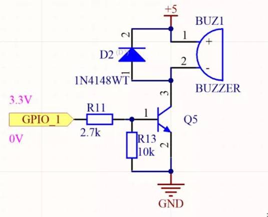
The following NPN triode, for inductive load, must be connected at both ends of the load a reverse continuous diode, because when the triode is turned off, the coil will self-induced to produce a high reverse electromotive force, and the continuous current diode provides a continuous flow path, while clamping the reverse electromotive force, to prevent breakdown of the triode.
The selection of continuous current diodes must be fast recovery diodes or Schottky diodes, both of which respond quickly.
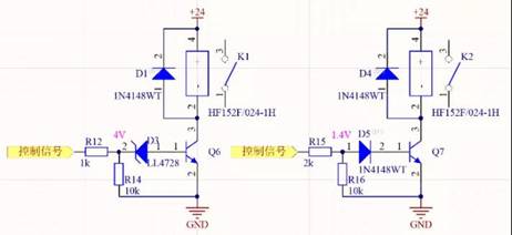
The NPN triode in the following figure, for some control signals are low voltage, may not be true 0V, generally within 1V, in order to ensure that the triode is completely cut off, have to add a reverse voltage regulator or forward diode in the triode b pole to increase the threshold voltage of the triode conduction.
According to personal experience, the digital signal of the push-pull output does not need to be added, OC output, diode output and delay control are necessary, usually the normal working current of the regulator is ≥1mA.
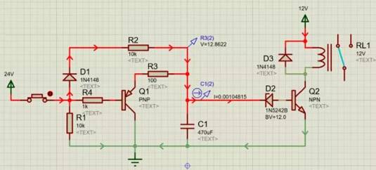
A simulation circuit for triode delay switching, fast switching off, D1, R2, C1, D2 form the delay switching on Q2 circuit, C1 voltage is 12V when Q2 is switched on, R3, Q1, R4, R1 form a fast switching off Q2 circuit, C1 through R3 and Q1 quick discharge.
gist
For NPN triode, without considering the triode, the partial voltage between the B-pole resistance and the pull-down resistance must be greater than 0.7V, and the same is true for PNP.
The b pole current must be ≥1mA to ensure that the triode is in a saturated state, at which time the Ic meets the large drive capacity of the triode.
In addition, for the amplification factor of the transistor β, refers to the output current drive capacity amplified β, such as 100 times, not the output current is really amplified 100 times.
免责声明: 本文章转自其它平台,并不代表本站观点及立场。若有侵权或异议,请联系我们删除。谢谢! Disclaimer: This article is reproduced from other platforms and does not represent the views or positions of this website. If there is any infringement or objection, please contact us to delete it. thank you! |

WeChat Official Account

WeChat Service
 Email
Email QQ
QQ 13823761625
