
From remote Internet of Things (IoT) -controlled garage door openers and Windows to satellite propulsion controllers, brushless direct current (BLDC) motors are increasingly being used in many different applications. For BLDC motors, the problem designers face is that the control algorithms needed to drive the motors are complex and often specialized. This makes it difficult for the average engineer to get such motors up and running in a reasonable amount of time.
Developers are often left with a choice between a software-based solution that runs on a microcontroller (which is a flexible software solution but also imposes a computational burden on the microcontroller), or the use of an application-specific integrated circuit (IC). The latter encapsulates the complete BLDC motor control function and transfers BLDC control from the main engine to it.
This article begins with a discussion of the differences between microcontroller-based software solutions and dedicated hardware chip solutions, followed by an in-depth look at how to use Allegro MicroSystems' A4964KJPTRT, a motor driver designed to simplify BLDC motor control for automotive applications. This article will show you how to interact with the A4964KJPTR-T and some best practices to avoid unexpected behavior。
BLDC motor minimalist introduction
BLDC motors provide efficient torque delivery over a wide speed range, with little noise and without the mechanical friction of brushed motors. Controlled by current rather than voltage, BLDC motors are versatile and vary in shape, size and cost depending on the application.
TRINAMIC MoTIon Control's QBL4208-41-04-006, for example, is a 24V, 4000RPM motor that delivers up to 0.06Nm of torque (Figure 1). The motor is lightweight (0.662lb) and offers developers a variety of motor control options, such as sensorless operation through the use of counter electromotive force (BEMF), or the use of built-in sensors that report position.
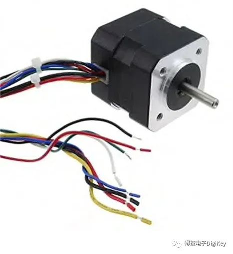
Figure 1: The QBL4208-41-04-006 is a 24V, 4000RPM BLDC motor that delivers slightly more than 0.06Nm of torque at top speeds. (Photo credit: TRINAMIC MoTIon Control GmbH)
For more torque, designers can use the QBL4208-41-04-0205, also from TRINAMICMoTIon Control (Figure 2). It's a 24V, 4000RPM BLDC motor that delivers slightly more than 0.25Nm of torque.
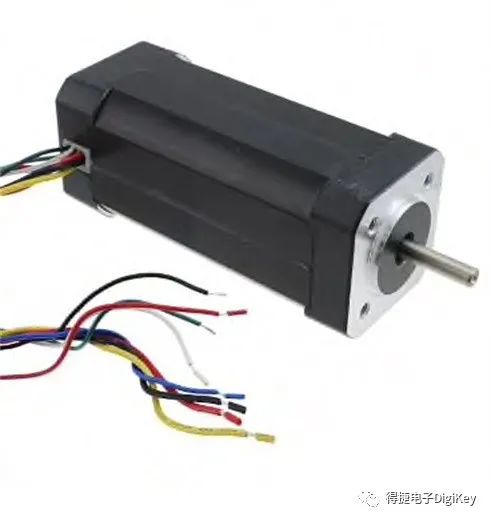
Figure 2: TRINAMIC MoTIon Control's QBL4208-41-04-025 is a 24V, 4000 RPM BLDC motor that delivers just over 0.25Nm of torque at top speeds. (Photo credit: TRINAMIC Motion Control GmbH)
The BLDC motor is driven by a three-phase wire, generating a magnetic field, which in turn pushes the permanent magnet to move the stator and turn the motor.
In theory, this sounds easy, but in practice, driving BLDC motors is quite complicated, and developers have no choice but to use a software framework to drive the motors, or choose a dedicated chip solution.
Software and dedicated chip solutions
When solving the problem of how to turn a BLDC motor, developers should consider several factors. These factors basically boil down to:
BOM cost and labor cost
Circuit board complexity and software complexity
Maintenance time and cost
Going the software route can be very attractive from a hardware perspective, as a dedicated chip solution adds some extra cost to the BOM. If you do not use a dedicated chip, you can eliminate this cost, spend very little money to buy a microcontroller, and put all the control algorithms into the microcontroller. This may seem like a win-win situation, but teams often fail to consider the full consequences of the decision.
Yes, the BOM cost is reduced, but there is an additional burden on the microcontroller to process BLDC status data and continuously drive the motor. If a microcontroller also samples other sensors, communicates with radios, and controls other devices, software development and maintenance costs can skyrocket without a little attention.
Software-based solutions in microcontrollers offer flexibility, however, as teams can fine-tune their motor control algorithms. And using software doesn't mean things are always going to be extremely complicated.
For example, typically, moving motor control algorithms into a microcontroller takes up more RAM and requires a lot of flash memory. However, if the team uses a microcontroller designed specifically for motor control, such as Texas Instruments' F280049CRSHSR motor control microcontroller, the algorithm is already built into the library of the microcontroller ROM. This means that the only additional code added to the application is the function calls that access the library, which does all the heavy lifting.
However, turning a BLDC motor is not just a matter of software, it also requires hardware. Figure 3 shows an example of an application using the C2000 microcontroller, where F280049CRSHSR is a member of the family. This illustration illustrates everything you need to drive a BLDC motor and the options available. In addition to the microcontroller, some kind of three-phase power stage is needed to drive the three phases of the BLDC motor to make the motor turn.
Figure 3: Texas Instruments' C2000 microcontroller is designed for motor control applications. This diagram is an application example, with the microcontroller in the middle and the rest being the required and optional circuits that drive the BLDC motor. (photo credit: TexasInstruments)
Using microcontrollers to drive motors is undoubtedly attractive, but what about dedicated hardware solutions? Let's look at Allegro MicroSystems' A4964KJPTR-T motor driver chip.
Allegro MicroSystems A4964KJPTR-T motor driver
Allegro MicroSystems' A4964KJPTR-T Motor driver chip is a dedicated BLDC motor driver that contains all the capabilities needed to drive the motor (Figure 4). Designed for automotive applications and paired with n-channel MOSFETs, the chip features sensorless start and commutation, so minimal external hardware is required. The A4964KJPTR-T also has a wide operating voltage range from 5.5V to 50V, which is not only suitable for automotive systems, but also covers almost all standard applications.
Perhaps the most striking feature of the A4964KJPTR-T is its ability to connect to a microcontroller or central electronic control unit (ECU) via a serial peripheral interface (SPI) to configure the various registers on which the motor runs. Obviously, this microcontroller does not need to be as powerful as a microcontroller running the motor control algorithm itself.
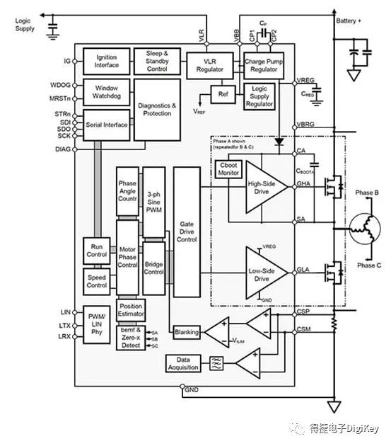
Figure 4: The A4964KJPTR-T BLDC motor driver operates at 5.5V to 50V and provides sensorless start and commutation. Motor speed can be configured using SPI or dedicated PWM signals. (Photo credit: AllegroMicroSystems)
It also makes sense that the A4964KJPTR-T motor speed can also be driven without SPI, simply by providing a pulse width modulation (PWM) signal. It has non-volatile memory to store motor Settings, which are loaded when powered on, allowing the motor to be controlled using only PWM signals.
From a configuration perspective, the A4964KJPTR-T has 32 addressable 16-bit registers, plus a status register. The status register is unique and transmits the first 5 bits on each SP read/write operation so that the software can check the general state and see if there are any faults or problems. When writing to the chip, the A4964KJPTR-T does not send back data, so it can read all status registers.
Of the 32 addressable registers, there are two special registers. Register 30 is a write-only register and register 31 is a read-only register. Write-only registers allow developers to set the required input, the duty cycle rate that drives the motor, with a value between 0-1023. The data in the read-only register changes based on the request data written to register 29 (that is, the read-back select register). This register allows the retrieval of various telemetry information, such as:
diagnosis
Motor speed
Average supply current
Supply voltage
Chip temperature
Demand input
Bridge peak duty cycle for application
Phase advance of application
In addition to these special registers, the remaining 30 registers allow adjustments to be made for specific motor applications and allow faults to be enabled or disabled, such as current limiting and gate drive faults.
Dedicated motor drivers make a lot of sense, storing the various configurations needed to run the motor in dozens of configuration registers. This greatly eliminates the software overhead that a microcontroller would otherwise incur and, perhaps more importantly, greatly reduces software development and maintenance costs. Driving a BLDC is nothing more than sending PWM (which does not impose any overhead on the microcontroller), or enabling the motor bit and providing SPI-based demand input to turn the BLDC.
A4964KJPTR-T Tips and tricks
The A4964KJPTR-T connection is simple, and here are a few "tips and tricks" developers should keep in mind to simplify and speed up their development, such as:
The status register is returned via the SPI interface each time it is written to the chip, rather than being used as a specialized addressable register. This means that the driver code needs to monitor the SPI bus SDO line for status information when writing to the chip.
Fault information is included in the status register, but when the microcontroller provides address access information, an overview of the chip status for each SPI transaction can be seen in the first five digits. This data can be used to determine if any problems have occurred.
There are two unique registers in the memory map, one read-only and one write-only. This is simple, but be careful not to try to read a write-only register; doing so will write any pseudo-data in the read sequence to that register.
The chip has a non-volatile memory that can be used to store default parameters. These parameters are loaded into RAM and used at boot time. To ensure that the chip is booted into the ready state most efficiently, the "safe" startup value should be written to the chip.
If the end device is used in a noisy or heavily radiated environment, it is a good idea to design the application code to periodically reconfirm the configuration data. The chip configuration is stored in RAM, which means it's vulnerable to cosmic rays, bit reversals, and all the weird, rare events that can happen in electronics.
Summary of this article
BLDC motor implementations for automotive, iot, or other applications are fairly common, but the drive can be complex. To cope with software complexity, developers can use dedicated BLDC motor drivers, such as the A4964KJPTR-T, where all motor control functions are packaged.
While the software is still required to interact with the chip, the microcontroller running the software only needs to set the configuration Settings, and the A4964KJPTR-T is responsible for driving the motor. When trying to use the A4964KJPTR-T, developers will find that following the "tips and tricks" provided can help save a lot of time and trouble.
免责声明: 本文章转自其它平台,并不代表本站观点及立场。若有侵权或异议,请联系我们删除。谢谢! Disclaimer: This article is reproduced from other platforms and does not represent the views or positions of this website. If there is any infringement or objection, please contact us to delete it. thank you! |

WeChat Official Account

WeChat Service
 Email
Email QQ
QQ 13823761625
