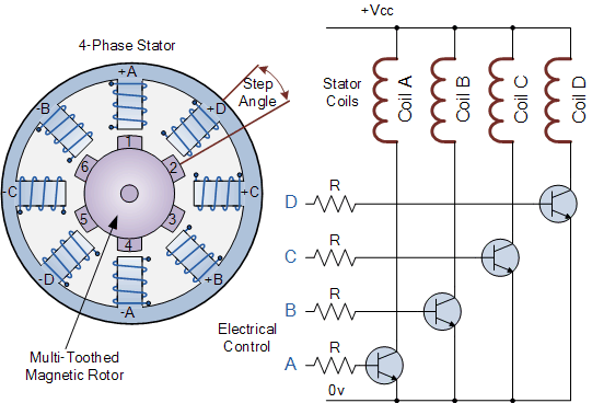
In the simple example of the variable reluctance stepper motor above, the motor consists of A central rotor surrounded by four electromagnetic field coils labeled A, B, C, and D. All coils with the same letter are connected together, so electrification (such as A coil labeled A) will cause the magnetic rotor to align with that group of coils.
By applying electricity to each set of coils in turn, the rotor can be made to rotate or "step" from one position to the next at an Angle determined by its step Angle structure, and by applying electricity to the coils in sequence, the rotor will generate rotational motion.
Stepper motor drivers control the step Angle and speed of the motor by energizing the excitation coil in A set sequence, such as "ADCB, ADCB, ADCB, A..." The rotor will rotate in one direction (forward) and by reversing the pulse train to "ABCD, ABCD, ABCD, A..." Etc, the rotor will rotate in the opposite direction (reverse).
Thus, in the simple example above, the stepper motor has four coils, making it a 4-phase motor with 8 (2 x 4) poles on the stator, spaced 45 degrees apart. The number of teeth on the rotor is six, and the tooth spacing is 60 degrees.
The rotor then has 24 (6 teeth x 4 coils) possible positions or "steps" to complete a full turn. Therefore, the step Angle above is: 360 o /24 = 15 o.
Obviously, more rotor teeth and/or stator coils will result in more control and finer step angles. In addition, by connecting the electrical coils of the motor in different configurations, full step angles, half step angles and micro-step angles can be achieved. However, in order to achieve microstepping, the stepper motor must be driven by a (quasi-) sinusoidal current, which is expensive to implement.
The speed of rotation of the stepper motor can also be controlled by changing the time delay (frequency) between the digital pulses applied to the coil, the longer the delay, the slower the full turn. By applying a fixed number of pulses to the motor, the motor shaft will rotate at a given Angle.
The advantage of using a delayed pulse is that no additional feedback of any kind is required, since the final position of the rotor can be accurately known by calculating the number of pulses supplied to the motor. This response to a set number of digital input pulses allows the stepper motor to operate in an "open-loop system", making it easy and inexpensive to control.
For example, suppose the stepper motor above has a step Angle of 3.6 degrees per step. To rotate the motor at an Angle of 216 degrees and then stop it again at the desired position, a total of only: 216 degrees/(3.6 degrees/step) = 80 pulses applied to the stator coil are required.
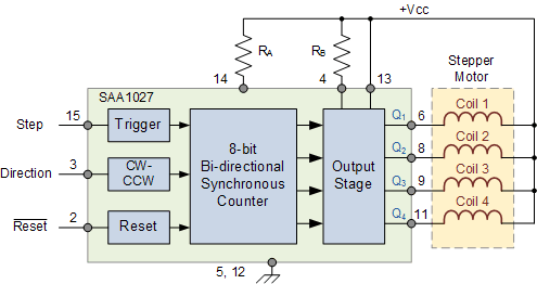
There are many stepper motor controller ics to choose from that can control the stepper speed, rotation speed, and motor direction. One such controller IC is the SAA1027, which has all the necessary counters and code conversions built in, and can automatically drive four fully controlled bridge outputs to the motor in the correct order.
The rotation direction can also be selected in a single step mode or continuous (stepless) rotation in the selected direction, but this places some burden on the controller. When using an 8-bit digital controller, there can also be 256 microsteps per step
SAA1027 stepper motor control chip

In this tutorial on rotary actuators, we examine brushed and brushless DC motors, DC servo motors, and stepper motors as electromechanical actuators that can be used as output devices for position or speed control.
In the next tutorial on input/output devices, we will continue to look at output devices called actuators, specifically those that use electromagnetic forces to convert electrical signals again into sound waves. The type of output device we will look at in the next tutorial is the speaker.
免责声明: 本文章转自其它平台,并不代表本站观点及立场。若有侵权或异议,请联系我们删除。谢谢! Disclaimer: This article is reproduced from other platforms and does not represent the views or positions of this website. If there is any infringement or objection, please contact us to delete it. thank you! |


