
We already know that alternating current has the following properties:
1. The size and direction are changed periodically, and the average value is zero; There are three elements: amplitude, angular frequency, initial phase;
2. There are instantaneous value representation, waveform diagram, effective value and vector method to describe AC.
3. Different alternating current may be in phase, reverse phase, orthogonal, or different from a certain Angle;
(4) Alternating current through resistance, inductance, capacitance and their combined circuit, the nature of the performance is different, mainly reflected in the phase, impedance, power;
The above four points are different from direct current, so AC has its own formulas, methods and properties in calculation.
Well, after reviewing the above questions, we can proceed to the following learning; The difference between resistance, inductance and capacitance lies in the following 6 aspects, we will explain and compare one by one.
I, resistance
1. Instantaneous value relation: u=RI, that is, the voltage through the resistance is equal to the product of the current through the resistance, note that u and i in this formula are all lowercase; This formula is rarely used in practice. It reflects the relationship between the instantaneous value of voltage and current.
2. RMS relation: resistance is equal to the ratio of voltage to current. Note that both voltage and current here are RMS values. This is a very practical formula, which we should master, and the calculation method of direct current circuit is the same;

3. Impedance: The impedance of the resistance is the resistance, why does it sound so awkward? As we said earlier, the impedance includes resistance, inductive reactance, and capacitive reactance, which are specific to different reactance components.

4. Vector diagram, it can be seen from the diagram that the voltage and current added to the resistance are in phase relationship;
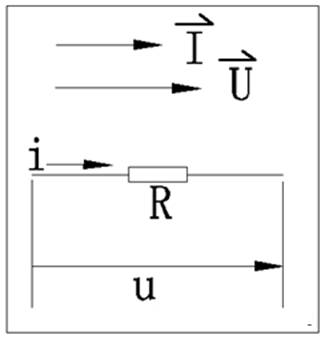
5. Power, equal to the product of voltage and current, or the square of current and resistance, P=UI, unit watt (W), this power is called active power, is the real power consumption of electrical energy, which is unique to the resistance, it is an energy-consuming component;
This is the value;
II, inductance L
1. Instantaneous value relationship

That is, the voltage applied to the alternating current is proportional to the rate of change of the current, and note that the instantaneous value of the resistance and u, i are lowercase; This formula has value and should be remembered; In addition, it is proportional to the rate of change, not the amount of change nor a fixed value, which is different from the resistance;
2. Effective value relation: the current added to the inductor is proportional to the voltage, equal to the inductive reactance, note that the voltage and current are all effective values, this is a very practical formula, we should master, it is consistent with the resistance in form;

4. Vector diagram: As can be seen from the diagram, the voltage applied to the inductor is 90° ahead of the current
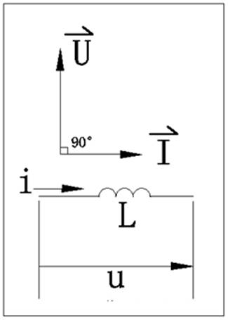
5. Power, active power P=0, that is, the active power of the inductor is zero, it is not an energy-consuming component, it is an energy storage component, its energy storage capacity is expressed by reactive power QL=UI, equal to the product of voltage and current, or the square of current and the product of inductive reactance, unit var, which is its important feature;
6. Power factor: Because the voltage added to the inductor is 90° ahead of the current, that is, the phase difference of the two is 90°, then cosφ=0;
IV. Capacitor C
1. Instantaneous value relationship

That is, the current through the capacitor is proportional to the rate of change of the voltage at both ends. Note that u and i are all lowercase like the instantaneous value of the resistance; This formula has value and should be remembered;
2. RMS relation: The current applied to the capacitor is proportional to the voltage and equal to the capacitive reactance. Note that the voltage and current here are both RMS values. This is a very practical formula, which we should master and is consistent

3. Impedance, capacitance and resistance, inductance, also has a hindering effect on the current, the size of its value is expressed by the capacitive reactance, f AC frequency, C capacitance, through this formula we can see that the greater the frequency of AC, the smaller the capacitive reactance, the direct current frequency is zero, the capacitive reactance is infinite, which is the capacitance of the separation through the interaction.

4. Vector diagram, from which it can be seen that the voltage applied to the capacitor lags behind the current by 90°
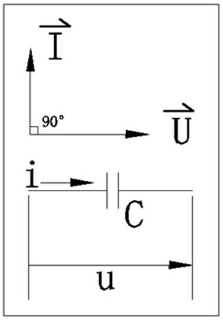
5. Power,P=0, that is, the active power of capacitors and inductors are zero, it is not an energy-consuming component, it is an energy storage component like inductors, its energy storage capacity is expressed by reactive power QL=UI, equal to the product of voltage and current, or the square of current and the product of capacitive reactance, the unit is also var.
6. Power factor, because the voltage added to the capacitor is 90° ahead of the current, that is, the phase difference between the two is 90°, then cosφ=0;
Through the above analysis, we see that alternating current through resistance, inductance, capacitance shown by the nature is very different, it is this difference, making their combination of nature diversification, showing a rich and colorful nature, has been widely used in electronic circuits, such as frequency selection, shift equal.
免责声明: 本文章转自其它平台,并不代表本站观点及立场。若有侵权或异议,请联系我们删除。谢谢! Disclaimer: This article is reproduced from other platforms and does not represent the views or positions of this website. If there is any infringement or objection, please contact us to delete it. thank you! |

WeChat Official Account

WeChat Service
 Email
Email QQ
QQ 13823761625
