
By Katter
When designing a DC-DC circuit, its efficiency is often considered, and there is a very big difference between 90% and 80% efficiency for the battery life of a consumer electronic device.
Sometimes when you look at the specifications of a chip, the nominal efficiency of the device can reach 92%. But in accordance with the same input, output voltage, load current to design the circuit, and then test the efficiency, why the test results are only 85%, 87%, that is, less than 90%?
In fact, the efficiency test of DC-DC is not only related to the chip, but also related to our test method, the selection of inductors and capacitors, and the working mode of the chip.
Today, in this article, we will talk about the 5 major losses of inductance, about the test method and the chip working mode, which will be shared in the subsequent article. The framework of this article is as follows:
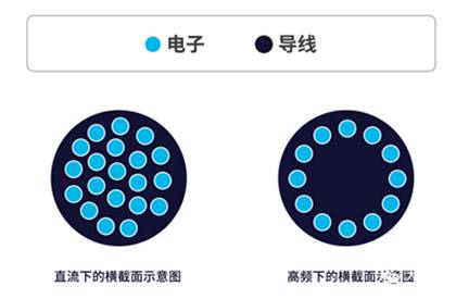
1. Skin effect
Two high frequency effects need to be understood before analyzing the loss of inductance - skin effect and proximity effect.
skin effect: When alternating current passes through the wire, the distribution of current on the cross section of the wire is uneven, the current density on the conductor surface is greater than the density in the center, and the higher the frequency of alternating current, the more obvious this trend is, this phenomenon is called skin effect (skin effiect), skin effect is also known as skin effect.
If the frequency of the current flowing to the conductor increases, the current will only flow through the surface of the conductor, the current density of the surface part increases, and the resistance value increases. We call this effect the skin effect, also known as the skin effect.
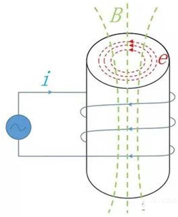
The essential reason for the skin effect is the correlation between current and magnetic field, which is represented by the following figure:

For a wire with current I, an alternating magnetic field is formed in the vertical plane of the wire. The alternating magnetic field generates induced electromotive force in the conductor, and the induced electromotive force forms eddy current in the conductor. Eddy current in the conductor is opposite to the change trend of the current and hinders the change of the current.
Inside the conductor, the equivalent resistance becomes larger, while the equivalent resistance on the conductor surface becomes smaller, so the current tends to flow on the conductor surface, but compared with the current flowing on the entire cross-sectional area of S wire, the flow on the surface means that the resistance of the wire is increased.
2. Proximity effect
Proximity effect: When multiple wires are adjacent, the magnetic field formed by each winding induces eddy currents, which will flow through the narrow area adjacent to the conductor current at high frequency, and the current density of the adjacent part increases and the resistance value increases. We call this effect the proximity effect.
As shown in the figure below, two wires in the same direction flow current in the same direction, the magnitude of the current in the position of the two wires next to each other is current I minus eddy current, and on the far side, the current is I plus eddy current.

The current distribution of the two adjacent conductors is when the current flows in the same phase. If the current of the two conductors flows in opposite directions, the flow of the cable between the conductors is as follows:
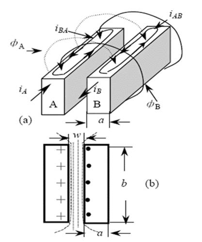
When the reflux conductor is near, the field vectors of the two wires will be added. Between two adjacent conductors, the magnetic field is strengthened in the same direction; On the outside of the two wires, the magnetic field is opposite and cancels, and the magnetic field is very weak or zero. Inside the conductor, it gradually strengthens from the outside of the two conductors to the inside, and the magnetic field is strongest when it reaches the inner surface of the conductor.
3. Iron loses copper
There are four main losses in the inductance, copper loss, iron loss, eddy current loss, hysteresis loss.
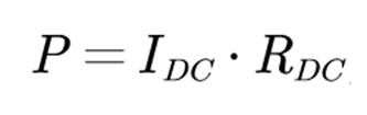
Copper loss: The loss caused by the resistance component
For an inductor, there are only two parts, the coil and the magnetic core, where the coil is copper loss and the magnetic core is iron loss. The loss (hysteresis loss and eddy current loss) generated in the magnetic core when the magnetic beam passes through the core is called the iron loss. Therefore, the iron damage is generated by the magnetic core.
4. Eddy current loss
Eddy current loss: Changes in the magnetic field due to electromagnetic induction will create a vortex current in the conductor's magnetic core. The energy that generates this current is converted into heat and becomes a loss due to the resistance of the core material. We call this loss eddy current loss.
5. Hysteresis loss
Hysteresis loss: If the magnetic field in the core changes or reverses, it will return to the original state with hysteresis (the hysteresis loop shown in the BH diagram of the magnetic core material). The energy expended for this hysteresis motion is lost as heat. We call this loss hysteresis loss, and the hysteresis loss is proportional to the area of the hysteresis loop.
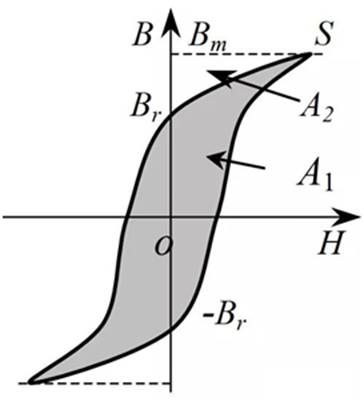
According to the previous analysis, the magnetic core will be magnetized in the magnetic field, the process of magnetization will make the internal magnetic domain find the direction of deflection, at the time of deflection, and the direction of the magnetic field is not much different from the magnetic domain has an 'elastic' rotation, which means that when the external magnetic field is removed, the magnetic domain can still restore the original direction; There are some magnetic domains to overcome the friction between the walls of the magnetic domain, rigid rotation, that is, when the external magnetic field is removed, the magnetic domain still maintains the direction of magnetization.
Therefore, when magnetizing, the energy sent to the magnetic field contains two parts: the former is converted into potential energy, that is, when the external magnetizing current is removed, the magnetic field energy can be returned to the circuit; The latter becomes to overcome the friction of the magnetic core heat consumption, which is the hysteresis loss. It can be seen from the fundamental hysteresis curve that when the area of the hysteresis curve is larger, the more energy is required to overcome friction and make rigid rotation.
免责声明: 本文章转自其它平台,并不代表本站观点及立场。若有侵权或异议,请联系我们删除。谢谢! Disclaimer: This article is reproduced from other platforms and does not represent the views or positions of this website. If there is any infringement or objection, please contact us to delete it. thank you! |

WeChat Official Account

WeChat Service
 Email
Email QQ
QQ 13823761625
