
Brushless direct current motors (BLDC) are widely used because of their long life, low maintenance and high efficiency. Based on this, BLDC is widely used in DIY and professional battery-powered motor products, such as power tools, garden tools, commercial and consumer multi-axis aircraft, battery-powered household appliances, robots, low-speed electric vehicles, etc. Different types of motors and control strategies are used in these products, so their voltages, torques, product specifications and so on are not the same, so is there a common control chip to achieve the control of different motor products?
Yes, this is Infineon's new three-phase motor intelligent driver chip 6EDL7141, which is an intelligent three-phase motor control gate driver that can be used in a variety of battery-powered motor control applications. 6EDL7141 gate driver supports 12-48V battery powered applications, this chip has a fully programmable design capability, can be configured with a large number of parameters, to achieve a variety of PWM control and braking mode control, and has complete protection functions, such as overcurrent, overheating, gridlock detection.
Next, you will learn about the overall architecture, characteristics, and innovative gate drive capabilities of this three-phase motor intelligent driver chip, and its GUI tool can be easily designed and online debugging, while the existing reference evaluation board can also allow designers to quickly realize product design and accelerate product market cycle.
Product Overview
A three-phase motor control gate driver IC for battery-powered BLDC motor control, the MOTIX TM 6EDL7141 is Infineon's latest three-phase motor control gate driver IC. The 6EDL7141 can be used to develop high-performance battery-powered products using BLDC or PMSM motors in many applications including cordless power tools, garden electric products and autonomous guided vehicles. The MOTIX TM 6EDL7141 has more than 50 parameters programmable using the SPI interface and can be fully parameterized to drive a variety of MOSFETs for optimal system efficiency.
The MOTIX™ 6EDL7141 offers great flexibility in a 48-pin VQFN package with operating voltages of 5.5-60V and configurable gate drives for both feed and pull currents up to 1.5A to effectively drive a wide range of MOSFETs to perfectly suit a wide range of applications. Thanks to the built-in dual charge pump, the grid driver supply voltage can be set to 7V, 10V, 12V or 15V, even at low battery voltages. The MOTIX™ 6EDL7141 gate driver parameters can also be adjusted to control the voltage swing rate to minimize electromagnetic interference to the system. All Settings of MOTIX™ 6EDL7141 can be changed quickly with an easy-to-use GUI.
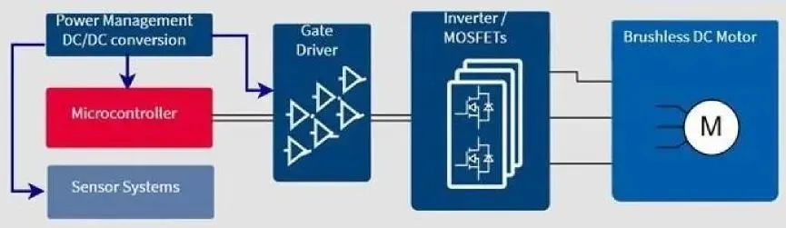
FIG. 1 Control application diagram of brushless DC motor

FIG. 2 Schematic diagram of typical application of 6EDL7141
The integrated step-down regulator requires only one external capacitor and inductor to power the microcontroller and Hall sensor in the motor, further reducing peripherals and the required PCB space. High-performance power tools also typically require high-precision current measurement using a precise ADC reference voltage. The MOTIX™ 6EDL7141 features an advanced linear power regulator architecture powered by an internal buck converter to provide optimal signal quality under any input and output conditions while optimizing power efficiency.
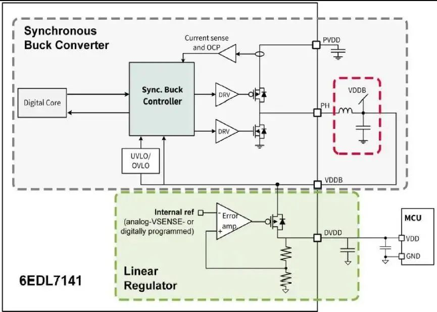
As you can see in Figure 3 and Figure 4, the MOTIX™ 6EDL7141 integrates a highly efficient synchronous Buck DC-DC converter to provide high voltage power to the entire system, with a wide input voltage range of 5.5-60V, and the VDDB can provide up to 600mA of current when the PVDD is ≥9.5V. An LDO regulator powered by the output of a Buck converter provides a low-noise digital power supply up to 300mA. As a system-level design, the power supply can be flexibly selected, such as: Buck or LDO output to power external components (MCU, Hall, etc.), to provide power to the supporting MCU, thus eliminating the need for power configuration.
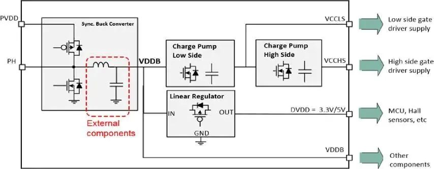
Figure 3 Internal power management architecture of 6EDL7141 chip
Adjustable grid drive parameters
The power supply in the system is powered by a step-down regulator that provides offset power to all three-phase high/low side drivers. The charge pump-based three-phase gate driver supports 100% duty cycle output, and thanks to the dual charge pump design, its gate driver supply voltage can be set to 7V, 10V, 12V or 15V via the SPI parameter, allowing the drive of standard MOSFETs even at low battery voltages. High and low side grid drive capacity up to 1.5A, built-in adjustable drive current design, which is also adjusted by SPI parameter Settings, can be combined with Infineon MOSFETs to achieve optimal system efficiency for different power level applications.
In addition to the ability to select gate driver pull and fill currents, the 6EDL7141 features an innovative and unique drive conversion rate control function that optimizes EMI and switching losses in battery-powered applications by controlling the rise slope and rise and fall time of the gate drive voltage. Dynamically optimized dv/dt enables MOSFETs to be used for optimal performance. This can greatly reduce the switching loss and facilitate the increase of operating frequency.
PWM mode and braking mode
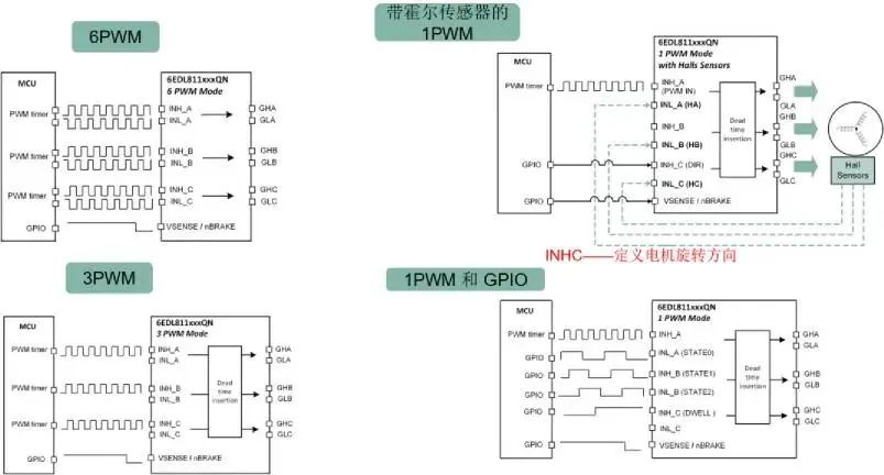
The 6EDL7141 offers 4 different PWM modes and one variant mode to meet different MCU requirements. The first mode is the 6 PWM mode, which drives the gate driver in the most classic way by using 6 PWM signals from the MCU.
The 6EDL7141 also has 3 other modes that simplify PWM generation on the MCU side through intelligence. These, together with integrated protection features, bring high reliability and faster development processes to drive applications. Intelligent dead zone time control will ensure that no breakdown will occur under any circumstances. A highly configurable braking mode provides a safe response to motor or system events. Different PWM modes are set by SPI.
// High side braking - all upper pipes are open, and lower pipes are closed
// Low side braking - all lower pipes are open and upper pipes are closed
// Alternate braking - Alternate between high and low side braking
// High resistance - All outputs are set to high impedance
The inverter through the problem needs extreme attention, the intelligent processing of dead time is also an effective means to effectively prevent the device through, 6EDL7141 dead time can be programmed, rising dead time and falling dead time can be independently programmed (through SPI). When editing the set dead time, you need to ensure that the dead time is sufficient to meet the requirements of the conversion rate configuration and the selected MOSFETs.
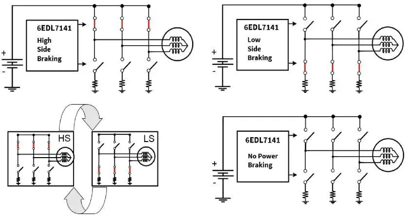
Figure 6 Braking mode
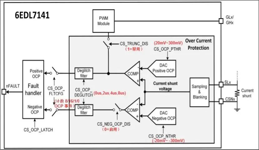
OCP overcurrent protection is a very important protection feature in motor applications, 6EDL7174 its internal OCP comparator mechanism has integrated highly accurate DAC reference voltage, positive OCP and negative OCP functions, PWM truncation, with anti-spike pulse timer, fault trigger event configuration, etc. Of course, OCP overcurrent protection also exists in the following locations: such as shunt or Rdson, DVDD, LDO OCP, buck converter OCP and other locations. At the same time, there is no lack of chip-powered UVLO, such as PVDD, gate driver power supply, DVDD LDO undervoltage lock protection, as well as system-level overtemperature alarm and protection shutdown, configurable watchdog, rotor lock detection based on Hall sensor input, memory failure, which together achieve systematic integrated protection for motor control. Improve the reliability of the motor system.
Graphical user interface (GUI) tools
Infineon provides GUI tools for motor drive control design, users can achieve device selection through the GUI interface, arbitrary configuration of parameters, which only need to write parameters to achieve visual parameter configuration and effect, greatly simplifying and saving design time. The adjusted parameters can be stored in the OTP. After the OTP operation is completed, some configurations can also be changed through the SPI command, 6EDL7141 provides up to 50 parameters that can be configured through the SPI.
With GUI and SPI, even non-professional motor control designers can easily design excellent motor control systems with 6EDL7141.

Evaluation boards speed up the design to market process
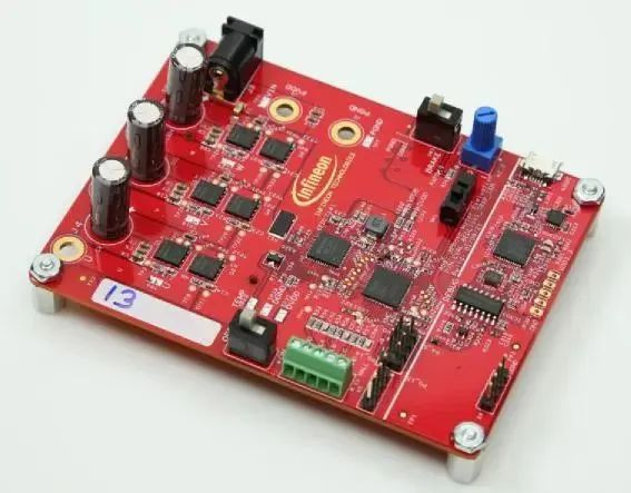
Infineon now offers an evaluation version of this three-phase smart driver, EVAL_6EDL7141_TRAP_1SH, which is designed for battery-operated brushless direct current (BLDC) motor drivers with trapezoidal wave control for applications such as wireless power tools. The evaluation board is used in conjunction with a motor containing an integrated Hall sensor for rotor position sensing, combining the XMC1400 series microcontroller with the 6EDL7141 three-phase smart driver IC and Infineon power MOSFETs. As can be seen from the design of the evaluation board, due to its high integration, the 6EDL7141 reduces the number of system group components and time to market, while significantly improving power density, system performance and peak power pulse capability.
The evaluation board features fully configurable operating parameters, integrated and configurable on-board power and gate drive outputs, and configurable protection modes. The built-in debugger connects directly to USB for debugging, and the evaluation board can be run independently or via the Infineon motor control GUI.
The evaluation board has A DC input voltage of 12 V to 24 V, a rated 18V, a maximum input current of 30 A, and a peak operating power of up to 500W. It can be used as a design reference for motor control applications including cordless power tools, garden products, autonomous guided vehicles, electric bicycles, drones and battery-powered robots.
Infineon's three-phase smart motor gate driver 6EDL7141, with perfect integration, a variety of integration functions, can significantly reduce the number of external components and costs, including built-in power converter, intelligent drive, sensing detection, comprehensive protection to improve reliability, configurable parameter implementation, for battery-powered motor drive applications to provide a convenient and fast design. Shorten product design and development cycle and time to market.
免责声明: 本文章转自其它平台,并不代表本站观点及立场。若有侵权或异议,请联系我们删除。谢谢! Disclaimer: This article is reproduced from other platforms and does not represent the views or positions of this website. If there is any infringement or objection, please contact us to delete it. thank you! |

WeChat Official Account

WeChat Service
 Email
Email QQ
QQ 13823761625
