
Introduction to brushless DC motor
Brushless DC motor is a typical mechatronics product, which is composed of motor body and driver. Brushless motor refers to the motor without brush and commutator (or collector ring), also known as commutator free motor. As early as the birth of the motor in the 19th century, the practical motor produced is a brushless form, that is, the AC squirrel cage asynchronous motor, which has been widely used. However, asynchronous motors have many insurmountable defects, so that the development of motor technology is slow. The transistor was born in the middle of last century, so the brushless DC motor using transistor commutator circuit instead of brush and commutator came into being. This new brushless motor is called electronically commutated DC motor, which overcomes the shortcomings of the first generation of brushless motors.
Working principle of brushless DC motor
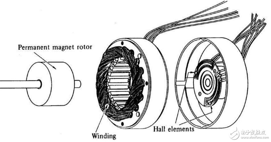
Brushless DC motor is a typical mechatronics product, which is composed of motor body and driver. The stator winding of the motor is mostly made of three-phase symmetrical star connection, which is very similar to the three-phase asynchronous motor. A magnetized permanent magnet is attached to the rotor of the motor, and a position sensor is installed in the motor to detect the polarity of the rotor. The driver is composed of power electronic devices and integrated circuits, etc. Its function is: to accept the start, stop and brake signals of the motor to control the start, stop and brake of the motor; The position sensor signal and positive and negative turning signal are accepted to control the on-off of each power tube of the inverter bridge to generate continuous torque; Receive speed instructions and speed feedback signals to control and adjust the speed; Provide protection and display and more.
Dc motor has a fast response, large starting torque, from zero speed to rated speed can provide rated torque performance, but the advantages of DC motor is its disadvantage, because the DC motor to produce constant torque performance under rated load, the armature magnetic field and rotor magnetic field must be maintained at 90°, which is by carbon brush and commutator. The carbon brush and commutator will produce sparks and toner when the motor is rotating, so in addition to causing component damage, the use of the occasion is also limited. Ac motors have no carbon brush and commutator, are maintenance-free, robust, and widely used, but the characteristics must be achieved with complex control technology to achieve the performance equivalent to DC motors. Today, the rapid development of semiconductors power module switching frequency is much faster, improving the performance of the drive motor. The speed of the microprocessor is also getting faster and faster, which can realize the control of the AC motor in a rotating two-axis cartesian coordinate system, and the appropriate control of the AC motor in the two-axis current component, which is similar to the control of the DC motor and has the equivalent performance of the DC motor.
Brushless DC motor Features:
1, can replace DC motor speed regulation, inverter + frequency conversion motor speed regulation, asynchronous motor + reducer speed regulation;
2, with the advantages of traditional DC motor, but also cancel the carbon brush, slip ring structure;
3, can run at low speed and high power, can save the reducer directly drive large load;
4, small size, light weight, large output;
5, excellent torque characteristics, medium and low speed torque performance is good, starting torque is large, starting current is small;
6, stepless speed regulation, wide speed range, strong overload capacity;
7, soft start and soft stop, good braking characteristics, can save the original mechanical braking or electromagnetic braking device;
8, high efficiency, the motor itself has no excitation loss and carbon brush loss, eliminating the multi-stage deceleration consumption, the comprehensive power saving rate can reach 20%~60%.
9, high reliability, good stability, strong adaptability, simple maintenance and maintenance;
10, bumpy vibration resistance, low noise, small vibration, smooth operation, long life;
11, no spark, especially suitable for explosive places, explosion-proof type;
12, according to the need to choose trapezoidal wave magnetic field motor and sine wave magnetic field motor.
PWM modulation mode of brushless DC motor is introduced
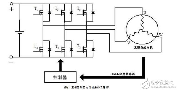
Figure 1 shows the driving part of the three-phase brushless DC motor, which mainly includes the collection of Hall information and the corresponding modulation of the three-phase inverter according to the Hall signal. The PWM switching sequence of the three-phase inverter and the duty cycle of the PWM are the main contents of the modulation. Different modulation modes have a great impact on the operation performance of the BLDC. In recent years, with the motor control system becoming more and more sophisticated, on the basis of the original common square wave 120-degree pulse width modulation, sine pulse width modulation (SPWM) and space vector pulse width modulation (SVPWM) appear, which reduces the motor pulsation and current waveform distortion. However, the algorithms of the latter two are more complicated. In this paper, the characteristics, principles and calculation details of the three modulation methods will be introduced one by one. The ON Semiconductor LC08000M chip integrates these three modulation modes and is suitable for BLDC drivers.
1. Square wave 120 degree pulse width modulation
The Hall value (6 changes per electrical cycle) is used to change the current flow direction of the UVW phase, but the current flow direction within the same Hall value is unchanged, and only the upper bridge of one phase and the lower bridge of the other phase can be switched on at any time. This control method is simple, but there is a maximum torque deflection Angle of 60 degrees

In the upper bridge and the lower bridge PWM switch control sequence is different, we can make the following 5 modes of optional installation.
LC08000M adopts PWM value transition mode in order to reduce the torque fluctuation during commutation, which can effectively reduce the rotation noise.
2. Sinusoidal Pulse Width Modulation (SPWM)
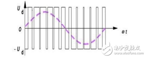
The DC voltage superimposed on the MOS tube can be controlled by PWM switch to be equivalent to sinusoidal voltage. Because the neutral point is 0, the phase voltage of the motor is also sinusoidal, so that the phase line current of the motor is also sinusoidal and the torque fluctuation is eliminated. According to the principle of area equivalence, sine waves can also be equivalent to PWM waves.
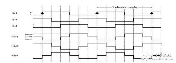
As shown in Figure 5, in this way we continuously adjust the duty cycle of the PWM to achieve the sinusoidal voltage effect.
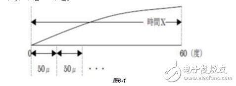
Sine pulse width modulation needs to know the detailed value of ωt, and we can only read the six general position information of 60°120°180°240°360° from the $Hall element, so we need to calculate the internal Angle within 60 degrees from the interval time of the previous Hall value changes. In the case of static start of the motor, we can not calculate the internal Angle information, so in the case of start, we still have to use the square wave 120 degree pulse width modulation mode to start, but after the motor gets a stable rotation, we can calculate the internal Angle, you can switch to the sine pulse width modulation mode.
Calculating the internal Angle method: As shown in Figure 6-1, first calculate the time required for each 60°, divide the time of PWM cycle to calculate the number of PWM within 60°, so as to obtain the value of the increase in the internal Angle when each PWM is increased within 60°, and add the large Angle value corresponding to the Hall value to get the current Angle; The UVW phase is 120° out of phase from each other.
免责声明: 本文章转自其它平台,并不代表本站观点及立场。若有侵权或异议,请联系我们删除。谢谢! Disclaimer: This article is reproduced from other platforms and does not represent the views or positions of this website. If there is any infringement or objection, please contact us to delete it. thank you! |

WeChat Official Account

WeChat Service
 Email
Email QQ
QQ 13823761625
