
Audio noise is a problem that many people encounter. The following introduces a noise issue caused by audio surround.
What is a ground loop
As the name suggests, a grounding loop is a physical closed loop in a system grounding scheme, generated from multiple grounding paths between circuits.
How is the ground loop formed
Caused by power supply and shielding

As shown in the above picture, the red line is the power supply line and the black line is the ground line. The audio of Device 1 and Device 2 are interconnected, and the shielded wire is connected to the ground for the first time. Device 2 also needs to supply power to Device 1, and the power ground wire is also connected, resulting in the black GND loop shown in the above picture.
For instance, in an application scenario: There are two wires connecting the audio amplifier to the PC. One wire is powered via USB, and the other is a 3.5mm headphone jack cable. Such a connection may have noise.
It is caused by 220V being connected to a GND wire and a shielded wire
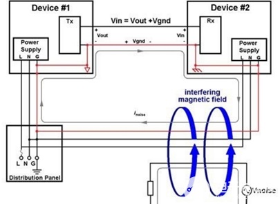
As shown in the above figure, both Device One and Device 2 have their own independent power supply systems. Originally, only the shielded wires between Device One and Device were connected to GND. However, since both were connected to a 220V power supply, a red ground loop as shown in the above figure was formed.
In conclusion, many complex application scenarios may cause ground loops. For instance, some products have metal casings, and the PCB boards are all connected to the metal casing through screw holes, which can also form ground loops.
How does the ground loop introduce noise
Why does the ground loop introduce noise?
The first is the antenna effect: since the ground loop can act as a large loop antenna, it can pick up noise from the environment and generate current on the ground loop. The ground is also composed of wires and is not a superconductor. It has ground resistance and ground inductance. When current flows through it, a voltage will inevitably be generated. This voltage is noise. After being amplified by the receiving equipment, this noise becomes quite considerable and sometimes can cause it to be completely unusable. It is worth mentioning that the 50/60 Hz magnetic field of the AC power supply is a common noise source picked up by the ground loop. The frequency range of sounds that human ears can hear is from 20Hz to 20,000Hz, so noise at 50Hz can be heard.
The second is power split: In the case of shared power supply, under normal circumstances, the ideal return path of the audio signal is the GND line (shielded line) of the audio, and the return path of the power supply is the power ground line. However, how could the circuit be so obedient? Since a ground loop is formed, the power supply return can be returned from the GND line of the audio. The amount of return depends on the impedance of the two paths. Just the power return flow. If the current fluctuation of the power supply is small, the noise generated will not be significant. After all, audio is an alternating current signal. If the current of the shunt is constant, no alternating current signal will be produced either. In most cases, the current, due to the different electricity consumption of the equipment at all times, is also an alternating current signal. Therefore, the current distributed to the audio ground wire is also an alternating current signal, which will form noise within the audio frequency range.
How to solve the ground loop noise
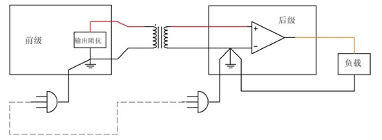
A. Use an audio isolation transformer: This method disconnects the ground loop
B. Single-point connection of the shielding layer to GND: Many audio cables have GND connected to both sides. If conditions permit, connect GND to one end and disconnect the other end. This approach also breaks the ground loop.
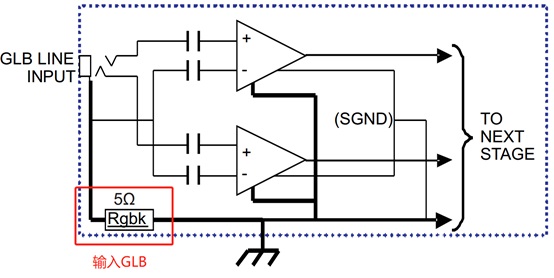
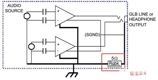
C. Using GLB circuit: The ground wire of the audio signal terminal is connected to the ground through a small resistor. For specific principles, please refer to the TI document "TI Ground Loop Break Circuits and Their Operation.pdf". Reply "GLB" on the public account to obtain this document. The principle of this method is to increase the impedance of the ground loop and let the noise mainly fall on that small resistor ----. It is applicable to circuits where the signal SGND and power PGND are separated.
免责声明: 本文章转自其它平台,并不代表本站观点及立场。若有侵权或异议,请联系我们删除。谢谢! Disclaimer: This article is reproduced from other platforms and does not represent the views or positions of this website. If there is any infringement or objection, please contact us to delete it. thank you! |

WeChat Official Account

WeChat Service
 Email
Email QQ
QQ 13823761625
