
Abstract
In many applications, preventing overvoltage is of vital importance. This article will explain how to use protection circuits to eliminate overvoltage.
Introduction
For instance, in a power distribution system, the rapid disconnection of high loads may lead to overvoltage. To protect other loads connected to the same power supply, it is recommended to take surge protection measures. Figure 1 shows the layout of a protection circuit, with LT4363 used at the front end of the electronic circuit to be protected. This example is derived from an industrial application with a rated power supply voltage of 24V.
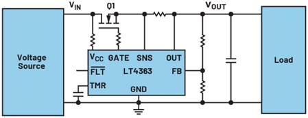
To optimize the component size, MOSFETs as small as possible are usually selected and their safe operation is ensured. This means that the selected MOSFET should neither be too large in size nor make full use of most of its SOA range in practical applications. For this reason, the controller IC must be capable of precisely identifying the working status to determine whether the operation of the MOSFET is within the safe range of the SOA. However, many controller ics merely measure the current flowing through the MOSFET. It would be even better if the voltage drop across the MOSFET could also be understood.
The working principle of this protection mechanism is to charge the timing capacitor on the TMR pin in Figure 1 based on the measured current and voltage drop. If the voltage on the capacitor rises above 1.275V, a warning will be issued. When the voltage exceeds 1.375V, the MOSFET will completely turn off to implement protection.
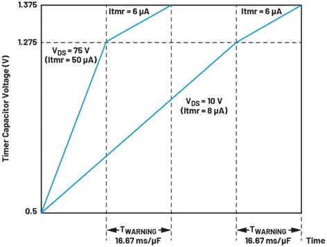
Figure 3 shows how the voltage on the timing capacitor of LT4363 in Figure 1 rises due to the VDS voltage on MOSFET Q1 in Figure 1. For the current flowing through the MOSFET Q1, there is also a similar charging diagram. These parameters can ensure that the SOA curve of the MOSFET is not exceeded, not only achiev
Conclusion
The overvoltage protection module may seem rather simple and unremarkable, but some subtle features can have a significant impact on the performance of overvoltage protection and the selection of MOSFETs.
免责声明: 本文章转自其它平台,并不代表本站观点及立场。若有侵权或异议,请联系我们删除。谢谢! Disclaimer: This article is reproduced from other platforms and does not represent the views or positions of this website. If there is any infringement or objection, please contact us to delete it. thank you! |

WeChat Official Account

WeChat Service
 Email
Email QQ
QQ 13823761625
