
A Brushless DC Motor (Brushless DC motor, BLDC) is a high-efficiency motor based on electronic commutation technology, featuring long life, low noise and high power density. Compared with traditional brushed DC motors, the physical brushes and commutators are removed, which increases the service life. In combination with FOC control, the maximum torque output at any Angle can be achieved, which greatly improves the motor efficiency. Moreover, the use of sine wave control in brushless motors can reduce ripple noise, making the motor operation smoother and more stable. With its performance advantages and the reduction in price, it has begun to be gradually promoted and applied in many occasions at present.
1.The basic composition of BLDC:
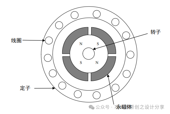
The mechanical structure consists of a stator, a rotor and a sensor. The stator is usually a three-phase winding coil (star or delta connection), which is fixed to the motor housing. The rotor is composed of permanent magnets (such as neodymium iron boron), without the need for brushes or mechanical commutators. In sensor-controlled systems, Hall sensors or encoders are used to detect the rotor position and assist in electronic commutation. In sensorless control, back electromotive force detection is used to determine the rotor position and assist in electronic commutation.
The motor body is as shown in the following figure:
The inverter circuit is driven by a controller (such as an MCU or a dedicated driver chip) to drive the brushless motor. Based on the rotor position information and in coordination with the core processor, the current direction of the stator winding is switched in sequence to generate a rotating magnetic field, which drives the permanent magnet rotor to rotate synchronously. Its essence is to control the direction of the magnetic field and drive the rotor through electromagnetic induction.
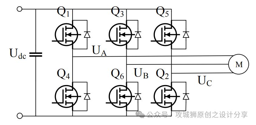
The control core is driven by a three-phase inverter: it is composed of 6 MOSFET/IGBT switches to form a three-phase full-bridge control. The driving circuit diagram is as follows:
4.Control mode:
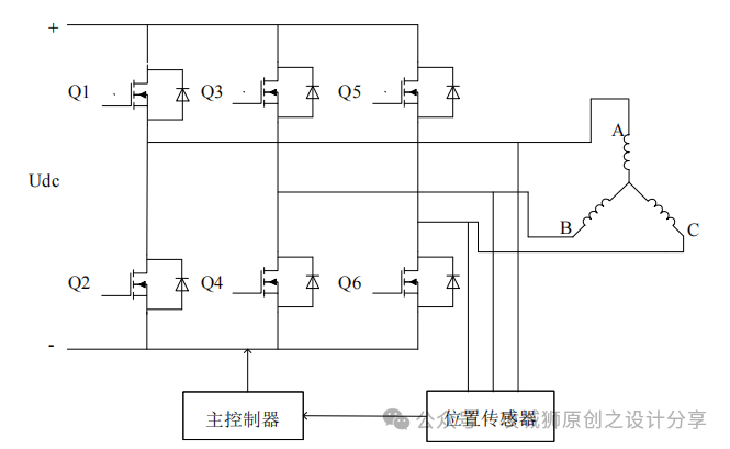
4.1. The overall control loop is as shown in the following figure:
4.22. Square Wave Drive (Trapezoidal Wave Drive)
Features: Simple control, low cost, but there are torque ripple and noise.
Implementation: The rotor position is detected by a Hall sensor. In a fixed sequence, generally known as six-step commutation, the power-on state of the three-phase windings is controlled and switched.
Typical applications: fans, power tools and other cost-sensitive scenarios.
4.3. Sine Wave Drive (FOC, Vector Control)
The rotor position is obtained by using Hall sensors or non-inductive algorithms (such as back electromotive force observers).
Features: Smooth sinusoidal current is generated through algorithms to achieve low noise, high efficiency and high dynamic response. The algorithm is more complex and has higher computing requirements for the processor. Software development is rather difficult.
Implementation: Through the switching state of the three-phase inverter in combination with the FOC algorithm, a sine wave is output to drive the brushless motor.
Typical applications: Precision control scenarios, su
5. Comparison of characteristics between DC brushed motors and brushless motors:

免责声明: 本文章转自其它平台,并不代表本站观点及立场。若有侵权或异议,请联系我们删除。谢谢! Disclaimer: This article is reproduced from other platforms and does not represent the views or positions of this website. If there is any infringement or objection, please contact us to delete it. thank you! |

WeChat Official Account

WeChat Service
 Email
Email QQ
QQ 13823761625
