
Summary of Audio Interfaces of Audio Codec - Digital Audio Interfaces
This article is based on the summary and study of the data manual of the commonly used Audio Codec TLV320AI3101 in the market, from which the input and output interfaces of the general audio codec and its internal signal processing flow are summarized more deeply. In this way, a more comprehensive understanding of audio codec and its audio processing flow is established.
The full text is divided into three parts:
• Analog audio input interface
• Analog audio output interface
• Digital audio interface
This article is the digital audio interface part among them.
• The digital audio data transmitted by the DSP is received through the digital audio interface, and after conversion by DA, it is played on devices such as speakers and headphones.
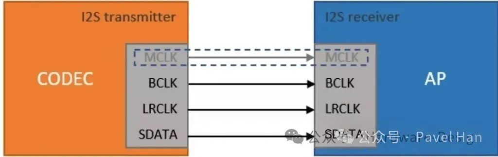
For Audio Codec, the most commonly used digital audio interface is the I2S interface. One I2S interface can be used to transmit dual-channel audio data containing two independent audio data streams. In order to utilize the hardware interface of I2S to simultaneously transmit more Audio data channels, some audio codecs also provide an audio transmission protocol for transmitting multiple audio data channels in the form of TDM time division multiplexing on the I2S hardware interface.
I2S(Inter-IC Sound) is a synchronous serial interface specifically used for the transmission of audio data, featuring simplicity, high efficiency and strong anti-interference ability. The I2S interface transmits digital Audio data, which is usually represented in the PCM (Pulse Code Modulation) format. In fact, it is the digital audio data after AD conversion of the voice data collected from the microphone in the Audio Codec. Or the digital Audio data received from the DSP, which needs to be converted to DA through the Audio Codec and then played by the speaker.
The parameters corresponding to the digital audio data transmitted via I2S include the sampling rate (such as 16KHz, 32KHz, 44.1kHz, 48kHz, etc.), bit depth (such as 16-bit, 24-bit, etc.) and the number of channels (such as stereo dual-channel). During the specific transmission process, the I2S interface synchronizes the transmission of audio data through clock signals. It uses multiple clock signals to control the sending and receiving of data, ensuring the accurate transmission of audio data.
The signal lines of the I2S hardware interface include:
• SDIN/SDOUT (Serial Data) : Serial data cable, used for transmitting digital audio data externally or internally.
• WCLK (Word Clock) : Word selection signal, used to indicate whether the data being transmitted currently is from the left channel or the right channel. Generally, WCLK transmits left channel data at high levels and right channel data at low levels.
• BCLK (Bit Clock) : Serial bit clock line, used to control the sampling rate of data. The audio data is sampled at the rising edge or falling edge of the BCLK.
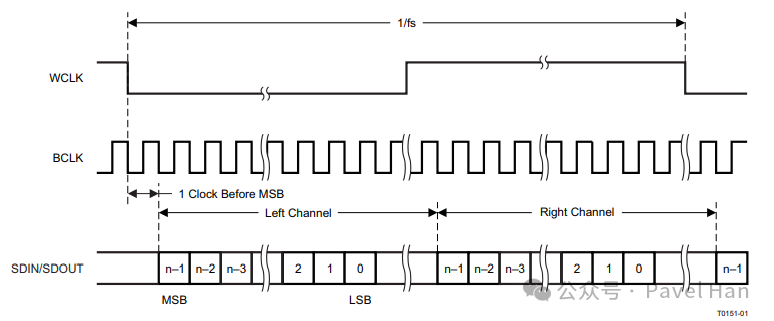
The following figure is the I2S working sequence diagram of TLV320AIC3101. In the I2S standard, the MSB data bit of the next channel begins to be transmitted after the WCLK edge (rising edge or falling edge) is delayed by one clock cycle (BCLK).
As mentioned above, one I2S interface can only be used to transmit two independent audio data channels in a left-right channel manner, forming a dual-channel stereo audio effect. However, in many cases, when our products (such as those with microphone array functions) need to transmit more independent audio streams, in addition to using multiple independent I2S interfaces, the TDM interface can also be used to solve this problem.
On the hardware interface, the TDM interface and the I2S interface share the same set of physical pins (DOUT/DIN, SCK, WS), but the data transmission protocols are different. The I2S mode can be used to transmit dual-channel (stereo) audio data. The TDM mode is used to simultaneously transmit multi-channel (2 to 8 channels) audio data using the same physical interface, multiplexing the same data line through time slot division.
In an audio Codec, the TDM interface can be used to transmit the sampled data of multiple independent audio channels on a single data line, and the data of each channel is transmitted in sequence according to the pre-allocated Time slots. During the specific working process, the TDM interface and protocol will divide the data transmission cycle into multiple time slots, and each time slot is assigned to an independent audio data channel. For example, if TDM supports 8 time slots, it can transmit audio data from 8 channels, and the 8 channels take turns using their own time slots to transmit data.
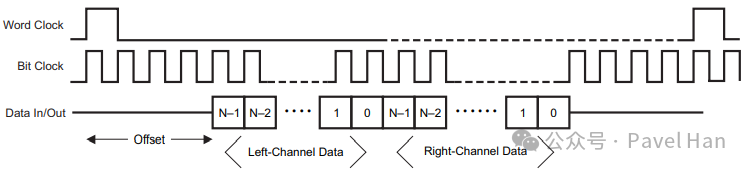
The following figure is the TDM data transmission timing diagram of TLV320AIC3101. It can be seen that for multi-channel audio Data transmission using the TDM mode, the same hardware interface and physical pins as I2S are used. However, instead of using the Word Clock to distinguish the left and right channels, the transmission time slots used for different audio streams are fixed at Data In and Data Out. Therefore, For upstream and downstream devices that use the TDM interface for multi-channel audio data transmission, it is necessary to negotiate and set in advance how many audio streams can be transmitted simultaneously and the time slots of each audio stream in the transmission sequence.
In fact, apart from the above-mentioned I2S interface and TDM interface, there is also a PCM interface for transmitting digital Audio signals on some Audio codecs (TLV320AIC3101 does not have a PCM interface). This interface is mostly used in voice communication and multi-channel data transmission scenarios.
The PCM interface is generally used to transmit uncompressed multi-channel (the biggest difference between the PCM interface and I2S is that it can support multiple channels more flexibly) linear PCM audio data, which can support various scenarios such as voice and music.
In the specific usage process, the typical application scenario of the PCM interface is to connect with audio devices in forms such as single-device multi-channel and multi-device multi-channel. Through a set of PCM interfaces, the transmission of audio data from multiple independent audio channels can be achieved. For example:
• One 8-channel ADC chip is connected to the Host through the PCM interface and transmits one channel of sampling data in each time slot.
• The Host connects four mono microphones via one PCM interface (each device occupies one time slot).
In terms of the hardware definition of the interface, the PCM interface is quite similar to the I2S interface and usually includes the following data cables:
• PCM_CLK (Bit Clock) : Generated and controlled by the main device, with a frequency of sampling rate × bit width × number of channels. For example, in the case of 16-bit, 8-channel and 48 kHz sampling rate, the frequency of PCM_CLK = 48k × 16 × 8 = 6.144 MHz.
• PCM_SYNC (Frame Synchronization) : Generated and controlled by the master device, it identifies the starting position of the audio frame, and the frequency is equal to the sampling rate.
• PCM_DIN (Data Input) and PCM_DOUT (Data Output) : Transmit multi-channel audio data.
From the data cables included in the above PCM interface, it can be seen that the definitions of PCM_CLK, PCM_DIN, and PCM_DOUT are no different from those of I2S. The main difference between the two lies in the WCLK of I2S and the PCM_SYNC of PCM.
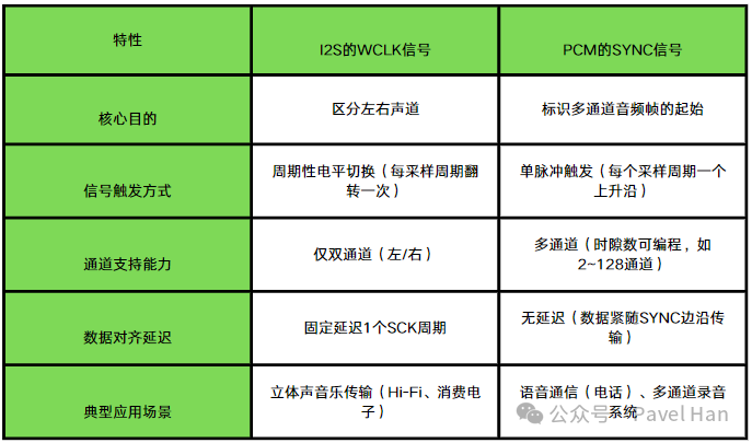
To thoroughly explain the differences between the two, it is necessary to first figure out what the audio frame in PCM_SYNC, which is used as the frame synchronization signal in the PCM interface, means.
The audio frames transmitted in the PCM interface are always initiated for transmission by a jump of PCM_SYNC (the jump edge can be programmably set), and an audio frame contains one audio sampling data of each channel among the multiple channels connected by the PCM interface. Each audio sampling data occupies a fixed time slot. The time slots occupied by each channel in the audio frame are set in the registers at both the Host and Device ends. In this case where the PCM interface is connected to multi-channel audio devices, an audio frame is divided into multiple time slots, and each time slot contains the audio sampling data of one of the channels. The entire audio frame is triggered by the PCM_SYNC signal to start a complete data transmission cycle (i.e., the cycle of this audio frame).
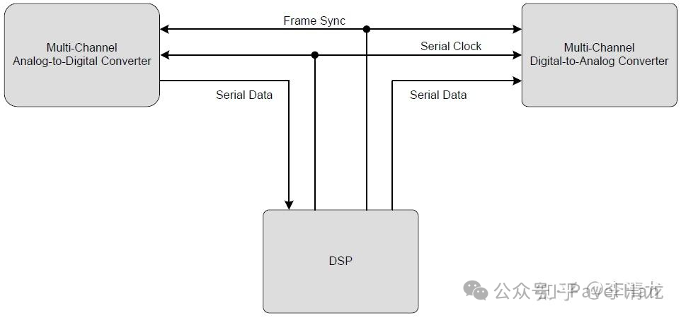
As shown in the following figure, it is a schematic diagram of the four-channel audio transmission connected by the PCM interface. A jump of PCM_SYNC (FS) initiates the transmission of a PCM Frame. A PCM Frame contains the audio sampling data of four independent channels, and the sampling data of each channel occupies a fixed time slot.
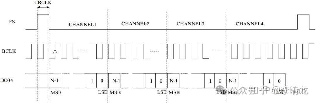
Essentially, the PCM interface also transmits audio sampling data from multiple channels using different time slots on a single DIN and DOUT line in the form of TDM time division multiplexing.
免责声明: 本文章转自其它平台,并不代表本站观点及立场。若有侵权或异议,请联系我们删除。谢谢! Disclaimer: This article is reproduced from other platforms and does not represent the views or positions of this website. If there is any infringement or objection, please contact us to delete it. thank you! |

WeChat Official Account

WeChat Service
 Email
Email QQ
QQ 13823761625
