
Author: Frederik Dostal, Senior Field Application Engineer
When designing a power supply, strict testing is very important. To complete this task, hardware measurement is indispensable. Of course, many errors may quietly occur during this measurement process. In this short article on power management techniques, we will study the influence of the connection lines between the power supply under test and the load. When performing rapid circuit board connection in the laboratory, its setup is usually as shown in Figure 1. At this point, a long connecting wire connects the power supply to be tested to the electronic load (as shown on the right side of the figure). Two wires are randomly placed on the laboratory workbench, and the circuit area is relatively large.
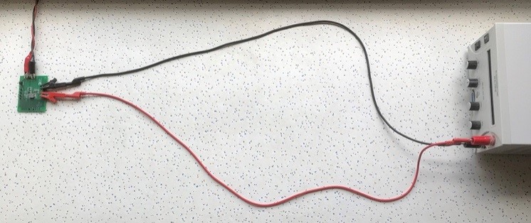
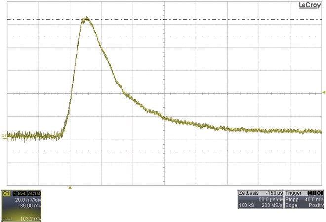
Figure 2. Carefully arranged connection wires between the power board and the load.
Figure 3 shows the voltage spikes in the AC-coupled output voltage during the load transient response, and the measurement Settings are shown in Figure 1. The peak voltage is approximately 103 mV. In contrast, Figure 4 shows the measurement results when the wires of the connecting lines are neatly twisted together (as shown in Figure 2). At this point, the voltage spike in the output voltage is only approximately 96 mV. This is equivalent to a difference of approximately 7 mV, indicating that the neat arrangement of the connection lines can lead to an improvement of approximately 7% in the transient test results of this load.
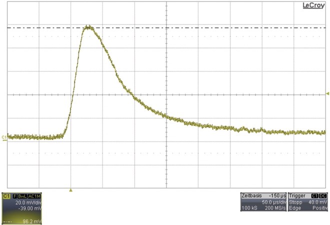
Figure 4. Transient response of the output voltage load when the connecting wires are carefully arranged (as shown in Figure 2).
Therefore, we can clearly see that a good measurement setup can provide more accurate results. In addition to the geometric arrangement of the connection lines between the power supply to be tested and the load, the cable length and the corresponding connection type (in this example, alligator clips or welded joints) are also very important. The shorter the wire is, the smaller the parasitic inductance will be, and the smaller the influence on the transient test results of the load will be. The shortest possible connecting wire should always be used.
The results show that neatly twisted wires will definitely have an impact on the measurement results. Therefore, it is worthwhile to spend extra effort twisting the leads for measurement Settings.
免责声明: 本文章转自其它平台,并不代表本站观点及立场。若有侵权或异议,请联系我们删除。谢谢! Disclaimer: This article is reproduced from other platforms and does not represent the views or positions of this website. If there is any infringement or objection, please contact us to delete it. thank you! |

WeChat Official Account

WeChat Service
 Email
Email QQ
QQ 13823761625
