
Light-emitting diodes (leds) are rapidly becoming the most popular lighting choice. Due to the US government's mandatory requirement for energy conservation, incandescent lamps have been largely phased out. LED lamps have been widely adopted because of their long lifespan (typically 25,000 hours) and ease of adaptation to various socket and shape requirements, replacing incandescent lamps. However, LED lighting control has some problems that incandescent lamps do not encounter. For instance, due to the much smaller current of the LED load, the common type of three-terminal bidirectional thyristor switch may encounter challenges in locking and maintaining current characteristics.
LED lights used for home lighting may require 7.5W (A19 bulb -450 lumens) or higher power, and a chandelier usually needs 4 to 10 bulbs. By contrast, the total power consumption of a string of 50 decorative Christmas lights might only be 4.8 watts. The LED floodlight used to replace the typical filament device for embedded ceiling lamps can produce 750 lumens of brightness, with a power consumption of only 13 W (BR30), while the power consumption of the old filament device is usually 65 W.
The AC circuit designed to control the LED light output using the new Q6008LH1LED or Q6012LH1LED series three-terminal bidirectional thyristor switch elements is very simple because only a few components are needed. All that is needed is an ignition/trigger capacitor, a potentiometer and a voltage transition trigger device.
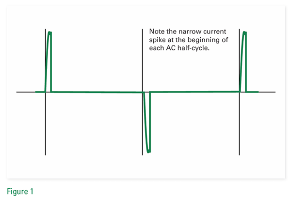
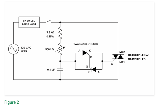
By using two reverse-parallel sensitive gated silicon rectifiers (SCRS) S4X8ES1 as voltage breakdown triggering devices, the control circuit can generate a wide range of optical level outputs. In addition, low-lag control can be achieved by using two reverse-parallel sensitive gated silicon rectifiers as trigger devices, as the two thyristors form a complete turn-off trigger. Figure 2 shows the circuit diagram of this control device, which might be an ideal choice for recessed floodlights (such as BR30 LED lights), which can be dimmed to produce a low-brightness output or raised to a full-brightness output close to 180°.
This circuit enables the bulb to turn on at almost a full Angle of 180° in each AC half-cycle. In addition, the RC timing on can be delayed to a small conduction Angle in each half cycle to achieve extremely low light output.
The Q60xxLH1LED three-terminal bidirectional thyristor series features low holding and locking current characteristics, enabling the three-terminal bidirectional thyristor to remain on at extremely low current levels. When the gates of two reverse-parallel sensitive gated silicon rectifiers (S4X8ES1) are connected together, an extremely low voltage trigger device with full breakdown voltage can be generated, thereby achieving extremely low lag. In this way, the potentiometer can be set to a low conduction Angle to conduct immediately when the line switch is turned off and on.
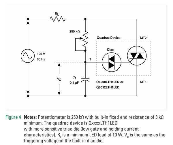
If a wide control range (from full bright to extremely dark) and low lag are not important for the application, the new Littelfuse Q6008LTH1LED or Q6012LTH1LED series Quadrac devices can be used to design simple variable light control. The Quadrac device is a special type of thyristor that combines a two-terminal bidirectional thyristor and a three-terminal bidirectional thyristor in one package. The circuit shown in Figure 4 combines the bidirectional thyristor trigger device and the three-terminal bidirectional thyristor in a TO-220 isolated mounting chip package, further reducing the number of components. Due to the high VBO of the bidirectional thyristor trigger device, this control circuit allows for a slightly lower fully open voltage and provides dimming functionality within the range of 175° to <90° for each AC half-cycle.
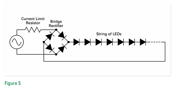
The LED light load of the AC circuit may be very simple, as shown in Figure 5; There may also be additional components for DC improvement, such as filter capacitors. The presence of additional components will determine whether the LED light load is dimmable. The simpler the LED light load is, the more likely it is to be dimmable, as the filter capacitor may increase the minimum DC current to the level where the thyristor device is locked, and the AC current cannot be reduced to less than the thyristor holding current.
Disclaimer: This article is reproduced from other platforms and does not represent the views or positions of this website. If there is any infringement or objection, please contact us to delete it. thank you! |

WeChat Official Account

WeChat Service
 Email
Email QQ
QQ 13823761625
