
LED digital display tubes are commonly used character display devices that can be directly integrated with CMOS, TTL and other integrated circuits for static and dynamic scanning display purposes. Figure 12-33(a) is a physical diagram of the LED digital display tube, and Figure 12-33(b) is the internal structure of the LED digital display tube. It is actually composed of 8 light-emitting diodes. Among them, 7 light-emitting diodes are arranged in the stroke segments of the shape of an "8", and the other light-emitting diode is in the shape of a dot and is installed at the lower right corner of the display to be used as a decimal point. Through different combinations of the brightness and darkness of the light-emitting diodes, Arabic numeral symbols ranging from 0 to 9 and various other characters that can be composed of these stroke segments can be displayed.
There are two different forms of internal structure for LED digital display tubes. One is the common anode display, and its internal circuit is shown in Figure 12-34(a), that is, the positive terminals of the 8 light-emitting diodes are all connected together to form the common terminal, while the negative terminals of the 8 light-emitting diodes are independently led out. Another type is the common cathode display, whose internal circuit is shown in Figure 12-34(b), that is, the negative terminals of all 8 light-emitting diodes are connected together to form a common terminal, while the positive terminals of each of the 8 light-emitting diodes are independently led out. There are two connection methods for the light-emitting diodes in LED digital display tubes:
Common anode connection method. Connect the anodes of the light-emitting diodes together. When in use, connect the common anode to +5V. At this time, if the cathode is connected to a low-level segment, the light-emitting diode will conduct and light up, but if it is connected to a high-level segment, it will not light up.
Common cathode connection method. Connect the cathodes of the light-emitting diodes together. When in use, ground the common cathode. At this time, if the anode is connected to a high level, the light-emitting diode will conduct and light up, while if it is connected to a low level, it will not light up.
The current-limiting resistor R in the drive circuit usually has its resistance value calculated based on the working current of the LED.
When the LED digital display tube is operating normally, the working current for each section is 5 to 10mA, the maximum working current for each section is 20mA, and the current when all strokes are lit is 35 to 70mA. The forward voltage is less than 2V. The light-emitting color of LED digital display tubes is mostly red, but there are also green and orange ones. LED digital display tubes are widely used in digital clocks, digital instruments and other digital displays.
To display numbers or symbols, codes need to be provided for LED digital display tubes. Since these codes are used to display glyphs, they are called glyphs codes.
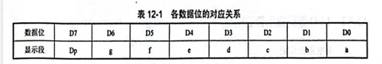
Seven light-emitting diodes, plus one decimal point, totaling eight bits of code, provided by one data byte. The corresponding relationship of each data bit is shown in Table 12-1.
The character (segment) codes of the LED digital display tube are shown in Table 12-2. When designing the program, Table 12-2 is stored as a table in the storage unit, and the display glyphs are changed by altering the content of the table. Therefore, it is more flexible to display the character shapes by software decoding.
The function of LED digital display tubes is to display characters. For example, time is displayed in the clock circuit, results are shown in the measurement and control circuit, and numbers are displayed in the counting circuit.
When choosing LED digital display tubes, the appropriate model and specification should be selected according to specific requirements. The external dimensions, luminous color, luminous brightness, rated power, working current, working voltage and polarity, etc. should all comply with the requirements of the application circuit. The polarity (common cathode or common cathode) of the selected LED digital display tube should be matched with its decoding drive circuit. The polarity of the LED digital display tube is usually indicated by the last digit after the model or the two letters before the model. The polarity marking methods for LED digital display tubes produced by different manufacturers are also different. This point should be particularly noted when making a selection.
免责声明: 本文章转自其它平台,并不代表本站观点及立场。若有侵权或异议,请联系我们删除。谢谢! Disclaimer: This article is reproduced from other platforms and does not represent the views or positions of this website. If there is any infringement or objection, please contact us to delete it. thank you! |

WeChat Official Account

WeChat Service
 Email
Email QQ
QQ 13823761625
