
-- Author: Terry Yuan Company: Junlong Technology
In the previous article "Universal Transmission Formats of ADI Audio in PCBA", we introduced the transmission formats of universal audio in PCBA, which involved multiple formats. This article will select one of the most commonly used digital transmission formats for relevant analysis to help everyone understand how to design reasonably in terms of software and hardware.
When designing audio within a PCB board, analog signals are often used as the front and back inputs and outputs. However, digital signals are more commonly used inside the board. For instance, we can see various aux, coaxial, and lotus port signal inputs. As long as audio needs to be processed, it is generally necessary to convert it into a digital signal, such as when we are using systems like FPGA, DSP, and single-chip microcomputers. In most cases, the implementation of a simple 2-channel system is relatively straightforward in terms of both software and hardware. However, when it comes to TDM8 and above, many customers will encounter stability issues. Next, we will explain to you in two sections - software and hardware - how to effectively avoid these risks.
Points to note in software configuration for TDM
As mentioned above, the TDM protocol typically consists of three wires (except MCLK), and some codecs may have four wires. The main clock harness is usually a constant input, while the other three are BCLK, SYNC, and SDATA (DATA usually has DTX or DRX, or can be flexibly configured as DTX or DRX). How should the transmitting end and the receiving end be configured to match? The following will introduce them one by one:
♦ Determine how many audio channels are to be transmitted
We need to select the TDM interface based on the number of audio channels to be transmitted. Generally, there are TDM2/4/8/12/16/32. The specific choice should be made according to the actual situation. Then determine the sampling rate and bit depth to obtain the exact bit clock data. For instance, for TDM16, with a sampling rate of 48khz and a bit depth of 32 bits, the determined BCLK frequency is 16 * 48khz * 32 bits = 24.576Mhz. In the driver, it is generally necessary to configure the specific TDM type, bit depth and sampling rate. Here, the configuration at the transmitting end and the receiving end needs to be consistent.
♦ Determine the type and polarity of SYNC
For frame synchronization signals, their frequency is generally the sampling frequency. For instance, in the TDM16 format, within one cycle of the frame synchronization signal, data from 16 channels can be transmitted. Meanwhile, it has pulse mode and 50/50 duty cycle mode. The pulse mode begins with an increase of one pulse from the first bit clock and ends at the end of the cycle. In 50/50 duty cycle mode, the high and low levels respectively occupy half of the channel. For specific details, please refer to the sample diagram in the datasheet. It also has a polarity, namely whether it is triggered by the rising edge or the falling edge. The transmitting end and the receiving end of this part also need to be consistent.
♦ Determine the polarity of BCLK
In the first point, we have already determined approximately what the clock of BCLK is. Next, we still need to proceed to the next step of polarity configuration. This polarity configuration actually corresponds to the SDATA bit, and it is necessary to distinguish between the driving edge and the sampling edge. Generally, the driving edge configuration at the transmitting end should be opposite to the sampling edge, and some formats should be the same. Specifically, it is necessary to check the description of this content in the data manual.
In fact, even if the configuration is incorrect, there will still be sound output. Basically, experienced engineers can tell that, or by analyzing the data in the data array, if there are no corresponding edges, the collected data is nothing more than an overflow or a missing digit. When a 1khz sine wave is detected to enter, the output data has this waveform characteristic, but there is no data at the high or low levels. It sounds like the original sound is small and the noise is large. In fact, this is the cause. In addition, the transmitting end and the receiving end of this configuration may be opposite or the same, so a comparison is required.
♦ Determine the format of the SDATA bit
The format mentioned here is closely related to MSB and LSB in data transmission, and this is in reference to SYNC. At the beginning of the SYNC cycle, we can choose formats such as delay 1 or left alignment and right alignment. Here, strict alignment is required; otherwise, the data will definitely be collected incorrectly. The configuration requires that the transmitting end and the receiving end remain consistent.
The above are basically some points to note in the software configuration of TDM. Of course, some chips may have added certain other functions on the basis of these configurations, which requires a specific check of the corresponding datasheet. For example, ADAU1452 has added the flexTDM function, and the TDM of AD2428 has added delay 1 SYNC and offset, etc. The purpose of doing this is basically to improve the compatibility of the chip IP. Some poorly performing manufacturers may not even be able to support TDM32 with their IP addresses, which can only support up to TDM8. However, generally speaking, the above configuration instructions can cover these basic configurations.
The key points to note in hardware design for TDM
Many people would say, "Isn't TDM just a few wires connected together?" Then IIS didn't have any problems running either, did it? Most customers may have rarely designed signals above TDM8, and extreme cases occur relatively rarely. This is because the audio in consumer electronics is less affected by the environment. However, in automotive electronics, the external environment is more complex, and some unstable phenomena often occur. The following text will focus on describing some problems and provide some solutions for everyone.
Why are resistors added at the transmitting end and the receiving end?
As shown in the following figure (Figure 1), we often add a resistor between IC1 and IC2. In fact, many engineers are not clear about why it is added and exactly how much it should be added. The following is a detailed explanation for everyone:
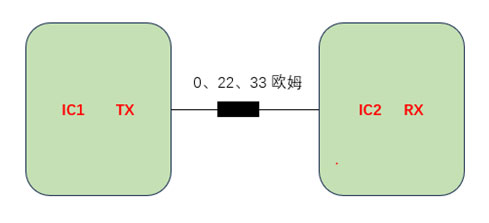
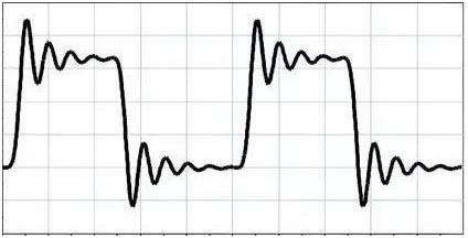
When designing the TDM IP interface of the chip, the impedance at the transmitting end is generally low, approximately ranging from 17 to 40Ω. The single-ended trace of the PCB is usually 50Ω, while the impedance at the receiving end is typically relatively large. This is a typical discontinuous and mismatched system. Therefore, we usually need to add a 22Ω resistor. It is added to the nearest transmitting end, which can basically maintain the continuity of the impedance as a whole. The typical waveforms that do not match are overrush and ringing, as shown in the following figure (Figure 2), and the risk of this problem is that it is easy to cause the receiving end to misunderstand the code.
Overall, the resistors on the signal lines are mainly used to match the impedance and reduce noise, while current limiting and protection functions are basically involved less frequently because the overall power is relatively small.
Should bypass or decoupling capacitors be added at the transmitting end and the receiving end?
Next, let's illustrate it through a real case. A certain customer has already designed all the product requirements for the power amplifier and it has entered mass production. However, after installing the product on the vehicle, it suddenly encountered problems such as no sound in low temperatures or some extremely extreme conditions. After a long period of investigation, it was found that the core problem still occurred in the bypass capacitor of the TDM.
Why add this capacitor? In automotive electronic products, we all need to pass automotive-grade certifications. At this point, a problem that troubles many engineers arises: when the EMI and EMC level requirements are too high to pass, engineers will consider adding some capacitors. On the one hand, because it is bypass or decoupling grounding, it can consume a considerable amount of energy, thereby reducing radiation. On the other hand, it can also reduce noise and improve electromagnetic compatibility.
In addition, in practical applications, attention should also be paid to the resonant frequency issue, especially the resonant frequency that is close to the signal frequency. After resonance occurs, it is most likely that the waveform of the threshold accessory of our signal will jitter, especially under some extreme conditions. The temperature drift property of the capacitor, in combination with its own ESR and the resistance in the circuit, forms an RC filter circuit. If this problem occurs, it is basically caused by the inability to determine the TDM signal or misalignment. So on this capacitor, those that do not require strict certification generally do not need to be added. For those that do need to be certified, the capacity should be appropriately increased or decreased, especially when the rising and falling edges show a backtick. Moreover, this frequency is usually very difficult to calculate as it is related to the transmission and reception, the routing, and the ESR of the capacitor itself.
In conclusion, when adding capacitors and resistors, one also needs to be careful, because if these conditions are not added properly, it will affect the waveform quality. When the resistance is increased too much, the waveform becomes a triangular wave. When the capacitance is increased too much, the waveform climbs into an arc, and the time for rising and falling edges is greatly increased, thereby further affecting the waveform quality.
To sum up, as long as a little attention is paid to the two points introduced above and the layout design of the hardware, a relatively stable product can generally be designed. Some customers have few problems because the bandwidth of most IIS is low enough and such situations rarely occur. At the same time, the fault tolerance rate is relatively high and the IP addresses designed by the chip manufacturers are sufficient for coverage. This also reflects from the side that in the design, if TDM8 is sufficient, there is no need to use TDM16 or 32, as it would increase some unnecessary risks.
Summary
Based on the above introduction, I believe everyone has gained an understanding of the TDM protocol and design approach. This format can be regarded as the cornerstone of general audio and is widely used. I hope it can be of some help to your design. At the same time, when making a choice, it is advisable to select chips that support TDM16 or 32 as much as possible. This is because the IP design bandwidth of such chips is generally better than that of chips that only support less than TDM8, especially in some high-performance SoCs or DSPS.
免责声明: 本文章转自其它平台,并不代表本站观点及立场。若有侵权或异议,请联系我们删除。谢谢! Disclaimer: This article is reproduced from other platforms and does not represent the views or positions of this website. If there is any infringement or objection, please contact us to delete it. thank you! |

WeChat Official Account

WeChat Service
 Email
Email QQ
QQ 13823761625
