introduction
Because of its small size, light weight and high energy density, Li+ lithium batteries are widely used in GSM/CDMA and high-end portable products such as digital cameras, camcorders and PDAs. They all need to establish a high-performance lithium-ion battery charger to ensure that the Li+ battery in use to avoid overcharging, overdischarge and other damage phenomenon, thus, it is required that the lithium battery charger has a strict and perfect protection circuit, in order to truly achieve the safety protection characteristics.
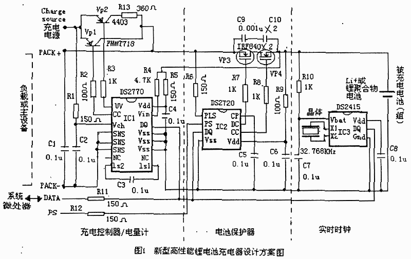
For this reason, the new DS2770 and DS2720 chips can be used to design a high-performance lithium battery charger combination with functions such as charge control, power control, power count, battery protection, timing and battery pack recognition. As shown in Figure 1, it can be used to replace the existing lithium battery protection/charge control circuit - charger - currently on the market. The following is a description of the functions and characteristics of the high-performance lithium battery charger combination design.
1 Charging combination circuit -- the composition of the charger
1.1 See Figure 1. The whole combined circuit is composed of three chips, DS2770 is a charge controller/coulometer, DS2720 battery protector and DS2415 real-time clock (RTC). They all share a common ground (Vss or Gnd), power supply (Vdd), and communication line (DQ or DATA). The role of all capacitors (from C1 to C10) and resistors (from R1 to R12) is to filter interference signals and protect ESD.

The charger's load (i.e. the main device) is powered by PACK+ and PACK- pins, while DATA communication between the charger and the main system is carried out through the standard l-Wire interface (labeled DATA). The PS pin of the DS2720 chip is connected to the on/off control of the main system and serves as the enable input of the charger (active at low level). The pin Charge·source in Figure 1 can be connected to the charging power supply, and the charging current can be limited according to the rated charging conditions of the battery, its charging voltage is up to 15V.
The entire charger consumes less than 100μA of typical current in working mode, and less than 20μA when it is at rest (that is, the lithium battery is not in charge).
1.2 The functions and features of DS2770 chip are introduced
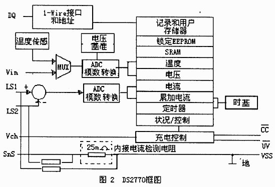
DS277 is a new chip that integrates battery metering and a lithium-ion or nickel-based battery charging controller, and its block diagram is shown in Figure 2. It also includes an optional 25mΩ detection battery for charging current measurement. The built-in measuring circuit detects voltage and temperature values as a criterion for charge termination and a criterion for a safe charging environment. All measurement results are stored in 16-byte SRAM memory, and its 40-byte EEPROM is reserved for the user. All information exchange with the main system is implemented through its standard l-Wire communication interface. The chip is low power consumption, working state power consumption is only 80μA, static current consumption is 0.5μA,
Its pin function description:
UV: The output when the battery voltage is detected as low, its low level is active.
CC: Charge control output, which is active at low level.
Vch: charge voltage input.
SnS: current detection resistance connection terminal.
Vdd and Vss: power supply end of the chip
Vss: ground end
DATA: data input/output end
LS1 and LS2: current detection inputs.
Vin: Input for battery voltage detection
2 About the protection characteristics of the charging circuit
See the middle of Figure 1. Two external n-channel MOSFET protection tubes (IRF840)VP3, VP4 and DS2720 chips are used to achieve safe protection of mono Li+ or lithium polymer batteries. That is, it can protect the battery from overcharging, excessive consumption, excessive discharge current and excessive temperature damage and other safety features. The DS2720 has a small current charging function to restore batteries that have been deeply discharged. The main system software can also detect the cause of battery failure through the DQ pins of DS2720 and DS2770 chips and report it to the user by the main system.
It should be noted that the MOSFET tube is connected to the high end of the charging combination circuit, located between the charging power supply and the positive end of the Li+ battery, as shown in Figure 1. To ensure that their data is not lost in the event of a protective failure or when the charging combination circuit is in sleep mode, it is best to power the DS2770 and DS2415 directly from a Li+ or lithium polymer battery. Otherwise, data will be lost when the MOSFET is turned off. The DS2720 chip has low power consumption, only 12.5μA in working state and 1.5μA in static state.
Its DS2720 pin features:
PLS Positive input of the battery pack
PS: The system (power) switch picks up the input, the low level is valid.
DQ: Data input/output.
CP: power storage capacity.
CC: charge control input
DC: discharge control output.
3 About charging and control
One of the functions of the DS2770 is to charge the battery with a simple current-limiting power source. By controlling the external PNP transistors (VP1(FMMT718 type) and VP2(4403 type), the DS2770 can charge a Li+ or lithium polymer-based battery pack with a constant current. Until the voltage rises to the factory's undefined 4.1V or 4.2V limit. It then fills the battery with a pulse charge.
T he DS2770 also provides an auxiliary charge termination control, that is, when the battery temperature exceeds +50 ° C or exceeds the maximum charge time set by the user. To start charging, simply connect a current-limiting power supply (up to 15V) to the chargesource.

4 About charging power count
The DS2770 can also be used as a high-precision coulometer. Current measurement is achieved with an internal 25mΩ detection resistor (see Figure 2) with a minimum resolution of 62.5μA and a dynamic range of up to ±2A average current.
In GSM/CDMA applications, the DS2770 can easily track the discharge current, its internal automatic compensation function maintains the accuracy of the measurement over the entire operating range of the chip, and enables real-time measurement of the accumulated current, voltage and temperature, together with the battery characteristics data stored in the EEPROM in the DS2770. Enables the host system processor to accurately calculate power while consuming very few system resources. And because the DS2770 is powered directly by the battery, the charge count information is not lost when the battery pack is removed or when the power supply fails due to a protective failure.
5 Real-time Clock RTC
The DS2415 provides an RTC with an accuracy of 2 minutes/month for the main system. It requires a 32.768kHz / 6pF external crystal connected to the Xl and X2 pins of the DS2415. Since the DS2415 is powered directly by the battery, this is an advantage that other charger circuits do not have. Placing the DS2415 clock on the inside of the MOSFET tube can provide a high-precision guaranteed clock for the main system and maintain correct time information even when the main system power is lost, eliminating the need to add a super capacitor or button battery as a backup power source in the main system.
DS2415 pin features:
Vbat Charging voltage input pin 2.5V-5.5V.
Others similar to the above are also indicated.
6 Save battery string information
The DS2770 contains 40 bytes of EEPROM for user access, while the DS2720 adds an additional 8 bytes. Battery pack manufacturers can use these Spaces to store relevant battery pack information, such as battery chemistry type, assembly date, battery specific information for charge counting, etc., once written to the EEPROM will be permanently locked, even in the event of main system power loss and ESD events can still ensure data integrity. In addition, each chip has a unique 64-bit sequence code for easy identification by the main system or charger.
Closing remarks
According to this scheme, the high-performance lithium battery charging combination-charger is characterized by simple operation, low cost, excellent performance, safety and reliability. It should be said that it has a high performance-price ratio.
免责声明: 本文章转自其它平台,并不代表本站观点及立场。若有侵权或异议,请联系我们删除。谢谢! Disclaimer: This article is reproduced from other platforms and does not represent the views or positions of this website. If there is any infringement or objection, please contact us to delete it. thank you! |


