
The notes for driver chip selection are briefly described
Date:August 3, 2025 Views:78
The drive chip of the electric drive system is the key component connecting the control system and the motor, and its main role is to convert the control signal into the power signal required to drive the motor, and ensure the efficient and safe operation of the motor. So its selection is very important.

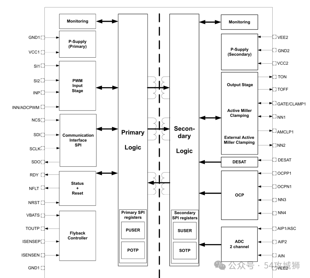
Image credit: Infineon 1EDI3050AS
The key factors of driver chip selection can be systematically summarized as follows:
1. Output current. To ensure that the chip can provide enough current and power to meet the load demand output capacity, it is generally recommended that more than 10A driver IC will have a built-in push-pull output.
2. Transmission delay of the primary secondary side. The maximum transmission delay, the smaller the better, affects the dead time.
3. Voltage range. Generally, the primary side is 5V power supply, the secondary side power supply range is adjustable, the maximum power supply is recommended to be more than 20V, compatible with Si and SiC drivers.
4. Support the maximum switching frequency, the higher the better, 40kHz or more is recommended to meet special needs such as boost charging.
Ⅱ、Protection function. To improve the reliability of the electric drive system, choose a chip with the functions of over-current, over-voltage, and over-temperature protection.
1. Upload a fault. It can be uploaded to the MCU through SPI or duty cycle. At present, most of the mainstream driver chips are SPI fault upload, SPI upload is fast but poor anti-interference, and occupies MCU resources, and the risk of false positive. Duty cycle upload is usually based on PWM signal, which has relatively slow data transmission speed and relatively strong anti-interference ability.
2. Support ASC. As far as possible, choose the chip that supports both the primary and secondary ASC, and the low-voltage side of the primary ASC can save the isolator.
3. Monitor the overvoltage and undervoltage of the primary and secondary power supplies, and have a fault response mechanism. It is recommended that the secondary power supply can be configured with over and under voltage, and can be compatible with Si and SiC drivers.
4. Dead zone interlock. Support the upper and lower bridge arm hardware interlock anti-straight-through protection, dead zone time can be configured.
5. Overcurrent protection. It has the overcurrent protection function. Generally, Desat protection is recommended. The Desat protection threshold can be configured by software.
6. Overtemperature protection. Fault alarm and wave blocking Optional.
7. Active clamp. Soft off or 2 level off after triggering.
8. Miller clamp. When the switching device is turned off, the drain voltage rises rapidly and is coupled to the gate through Cgd, resulting in overvoltage. The Miller clamp circuit is quickly switched on by an auxiliary switch to clamp the gate voltage within a safe range and prevent overvoltage damage.
9 Two level and soft off. Essentially, by controlling the slope of the gate drive waveform when it is turned off, reducing dv/dt or di/dt) to reduce the peak voltage and current generated during the switching process, thereby protecting the device from the influence of overstress. Choose chips with configurable times and thresholds whenever possible.
10. PWM monitoring. Monitor the path from PWM input to PWM output to the gate of the power module, and choose OSM (three-state) + gate monitoring as much as possible.
Ⅲ、Basic functions.
1. Package form and size. Choose the appropriate package, the smaller the better, need to consider the heat dissipation and installation method.
2. High voltage insulation. The high and low voltage electrical gap and creepage distance must be greater than 5mm.
3. Maximum working temperature. Not less than 150℃.
4. Functional safety. Support system to ASIL D.
5. Primary side isolation withstand voltage. The higher the better, support 800V system whenever possible.
6. Original secondary CMTI. The higher the better, the faster the SiC opening speed.
7. Primary side isolation. Generally, magnetic isolation and capacitance isolation, ST and TI capacitance products are mostly, and other manufacturers have more magnetic isolation. Magnetic isolation is more resistant to interference, but the cost is relatively higher.
Ⅳ、Advanced features.
The highly integrated design of the driver IC helps to improve the robustness and reliability of the electric drive system.
1. Support ADC sampling. Generally, it can be used for bus voltage backup redundancy sampling and temperature sampling of power module, which can save the isolator and its peripheral circuit, and achieve the purpose of reducing cost and volume.
2. Integrated flyback power chip. Similar to the STGAP4 driver IC used by the fourth generation Tesla, the flat transformer with small magnetic core can achieve volume and cost benefits according to the appropriate power supply.
3. Intelligent drive resistance adjustment. The drive parameters can be adjusted in real time according to voltage, current and module junction temperature, so that the electric control can achieve the optimal output efficiency.
4. Active discharge function. Through Vgth monitoring and Desat-Vce status monitoring, the switching frequency and duty cycle can be adjusted to achieve the purpose of quickly discharging the capacitor charge of the bus. Eliminating active discharge resistance and peripheral circuits to achieve volume and cost benefits.
免责声明: 本文章转自其它平台,并不代表本站观点及立场。若有侵权或异议,请联系我们删除。谢谢! Disclaimer: This article is reproduced from other platforms and does not represent the views or positions of this website. If there is any infringement or objection, please contact us to delete it. thank you! |

WeChat Official Account

WeChat Service
 Email
Email QQ
QQ 13823761625
