
Why is the motor surge current so high?
Although commonly understood, this fact seems to contradict common sense: the slower the movement (the less work is done over time), the less energy is used and therefore the lower the power consumption. The lower the power of a fixed voltage source, the lower the current consumption. Even the commonly used formulas related to torque, power, and RPM state:
Power = Torque (au) imes RPM
This equation also seems to associate low RPM with low power consumption.
Using these fundamental physics equations, it seems difficult to prove the apparently measurable, realistic reason why the inrush current is so high.
Motor coil impedance
In any motor, one component moves while the other remains stationary. In most motors, this means that the central axis is the rotor (rotation) while the housing remains stationary (stator). This is not the case in many brushless motors because the outside rotates; However, this article will mainly discuss induction motors.
The coils that make up the stator winding are wound around the ferromagnetic poles. This creates an RL circuit, some of which is the resistance of the wire itself, as well as the natural induction of the coil formation. When a voltage is applied to the wire, the magnetic field acts on the ferromagnetic metal and generates reactance (blocking the flow of current).
Figure 2. Three-phase motor with stator winding around iron pole.
Here, I have a motor wired for a three-phase 480 V input, with a resistance of 16.5 Ω measured between the T-leads. This? The FLA (ampere) rating of the HP motor is 1.5 A at 480 V. This equates to a total impedance of 320 Ω, much higher than the 16.5 Ω resistance of the coil itself.
This additional resistance is due to the induced reactance of the motor (both stator and rotor).
How do we know that? If the impedance is caused only by the windings and poles of the stator, then there is no difference between a stopped and running motor. As the motor accelerates, the resistance (and reactance) increases, so the current conversely decreases.
Measure the resistance of the motor windings between the 480 volt T-leads
Figure 3. Measure the motor winding resistance between T-leads, configured at 480 V.
Reverse voltage or reverse electromotive force
When the motor is running at full speed, a load is applied to the inductor, causing the inductor to consume energy to reverse the polarity of the rotor core laminate. In other words, it must consume more energy to rotate the axis and polarize the metal at the same time.
The load effect can also be demonstrated with a small DC motor: rotate the shaft while keeping the wire disconnected (no load), and it will rotate easily. Attach a light bulb or resistor to a wire, and rotation of the shaft becomes more difficult. When a magnetic field generates energy and converts it into light, heat, or motion, it creates significant drag.
In an induction motor, this counter electromotive force (EMF) provides enough resistance to reduce the current from extremely high starting values to nominal "full load" amperes at full speed.
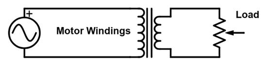
Another common analogy is to observe the effect of a transformer under no-load and full-load conditions. When there is no connected load, the core can be polarized with almost no force, and the power supply current will be high. When a variable load is connected and slowly increased, the load current drops and so does the power supply current.
If increasing the load does increase the back electromotive force, should a free-rotating motor that disconnects the load have a higher current and potentially blow the power fuses and circuit breakers?
When energy is consumed to move a load, this is called power. If the motor is unloaded, the power generated is very small. The rotor certainly has a back electromotive force, but the power requirements of the motor are much lower. Since the power equals:
[Voltage multiplied by current]
... And the voltage of the main power supply remains relatively unchanged, and the current will be low.
Therefore, the current of the no-load motor is reduced because the power required and produced by the motor is lower. The current of the load motor will be reduced because the heavier load will generate the back electromotive force.
However, in both cases, usually the no-load motor consumes less current than the same motor under load.
Second question: Is the high current due to acceleration or just RPM?
In the course of physics kinematics, commonly used equations are as follows:
[Force = mass times acceleration]
... Or...
[F = M times A]
If there is no acceleration (or constant motion), no additional force is required, so the power should be minimized. Therefore, if the motor is stopped, the current should be small. Only the brief moments when the motor is accelerating are periods of high surge current.
However, any electrician who has dealt with the current of an over-locked motor (or rotor lock) knows that a stopped motor can still consume a lot of current and cause failure. This proves that while acceleration requires more power and increases current, the rotor's speed (rather than acceleration) must have a large effect on current consumption.
Motor current fault
In most cases, this high starting current is expected and normal. Many motor starters have circuit breaker curves that allow high current to be generated for a short period of time while consuming both the motor and the load.
Repairing a faulty motor is a time-consuming and expensive process. Understanding how, when, and why these high current conditions occur can help reduce the cost and harm of these common problems.
免责声明: 本文章转自其它平台,并不代表本站观点及立场。若有侵权或异议,请联系我们删除。谢谢! Disclaimer: This article is reproduced from other platforms and does not represent the views or positions of this website. If there is any infringement or objection, please contact us to delete it. thank you! |

WeChat Official Account

WeChat Service
 Email
Email QQ
QQ 13823761625
