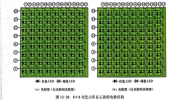
Two color dot matrix display has two types: common positive type and common negative type. Figure 13-20 shows the circuit structure of 8×8 two-color dot matrix display. Figure 13-20 (a) is a common positive dot matrix display, with 8 rows and 16 columns. The positive pole of 16 leds in each row (two leds form a light point) is connected to a common line, there are 8 common lines, and the negative pole of 8 leds in each column is connected to a common line. There are 16 common lines in total, and the common positive dot-matrix display is also called the common positive row and common negative dot-matrix display. Figure 13-20 (b) shows the common negative dot-matrix display, with 8 rows and 16 columns, the negative pole of 16 leds in each row is connected to a common line, there are 8 common lines, and the positive pole of 8 leds in each column is connected to a common line, there are 16 common lines. The common negative dot-matrix display is also called the common negative row common positive dot-matrix display.

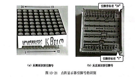
The 8×8 two-color dot matrix display has 24 pins, 8 row pins, 8 red column pins, and 8 green column pins. The 24 pins are generally divided into two rows, and the pin number identification is similar to that of an integrated circuit. If the pin number is identified from the side, it should be facing the side of the dot matrix display with characters and pins, the first pin on the left is 1 pin, and then it is 2, 3···24 pins counterclockwise, as shown in Figure 13-21 (a). If the pin number is identified from the back, it should be facing the characters on the bottom of the dot matrix display, and the first pin in the lower right corner is 1 pin. Then clockwise is 2, 3... Pin 24, as shown in Figure 13-21 (b), some dot matrix displays will also mark the pin number next to one and one pin.

Identification and detection of column pins
In the purchase of dot matrix display, you can understand the type of dot matrix display and column pin number, so that businesses to provide the same as Figure 10-20 dot matrix display circuit structure pin diagram, if you can not understand the type of dot matrix display and column pin number, you can use a multimeter detection, both can use a pointer multimeter, can also use a digital multimeter.
The lattice display is composed of many leds, and the on-voltage of these leds is generally 1.5 ~ 3.5V. If the digital multimeter is used to measure the dot matrix display, the diode measuring stop should be selected. The red pen of the digital multimeter is connected to the positive electrode of the power supply in the meter, the black pen is connected to the negative electrode of the power supply in the meter, and the red and black pen are connected to the positive and negative electrode of the LED respectively. Generally, the display is 1.500 ~ 3.500V (or 1500 ~ 3500 mV), on the contrary, the LED will not be conductive, and the multimeter displays the overflow symbol "OL" (or "1"). If you use a pointer multimeter to measure the dot matrix display, you should choose R×10k stop (other electrical blocks provide voltage only 1.5V, can not make the LED on), the red pen of the pointer multimeter is connected to the negative electrode of the power supply in the meter, and the black pen is connected to the positive electrode of the power supply in the meter, which is the opposite of the digital multimeter, when the black and red pen are connected to the positive and negative electrodes of the LED, LED will be on the light, the resistance indicated by the multimeter is very small, on the contrary, the LED will not be on the light, the resistance indicated by the multimeter is infinite (or close to infinity).
Take the digital multimeter to detect the red and green two-color dot matrix display as an example, the digital multimeter selects the diode measurement gear, the red pen does not move the first pin of the dot matrix display, and the black pen measures the remaining 23 pins in turn.
(1) If the overflow symbol "OL" (or "1") is displayed on the multimeter for 23 measurements, the red and black watch pens should be switched, that is, the first pin of the black watch pen does not move, and the red watch pen measures the remaining 23 pins in turn.
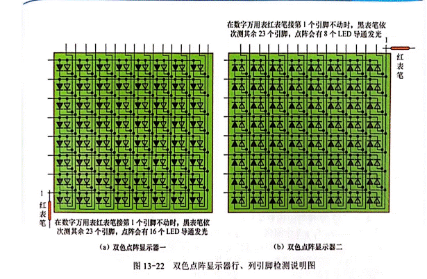
② The multimeter displays the number in the range of 1.500 ~ 3.500 for 16 times, and the dot matrix display LED emits light for 16 times, that is, there are 16 leds that emit light, as shown in Figure 13-22 (a), indicating that the dot matrix display is a common positive type, the first pin connected to the red pen is the row pin, and the row where the 16 luminous leds are located. 1 is the row of the pin, the measurement LED light of the 16th pin for 16 column pins, according to the light LED column and light color, distinguish each pin is which column of which color column pins. When measuring, the other 7 pins of the multimeter display overflow symbol "1" (or "OL") are row pins, and then connect the red watch pen with the first pin to one of the pins, the black watch pen is connected to the identified 8 red column pins or 8 green column pins, and check which row of the 8 LED lights, and the red watch pen is connected to the row pin. The remaining 6 rows of pin recognition are the same.
(3) The multimeter displays the number in the range of 1.500 ~ 3.500 for 8 times, and the dot matrix display LED emits light for 8 times (there are 8 LED conduction light), as shown in Figure 13-22 (b), indicating that the dot matrix display is a common negative type, and the first pin connected to the red watch pen is a column pin. When measuring, the 8 pins of the LED connected to the black watch pen that will glow are row pins, and the corresponding pins of the row in which the luminous LED is located are row pins of the row. When identifying 16 column pins, the black pen is connected to a row pin, and the red pen measures the 16 column pins in turn, and distinguishes which column and which color of each pin according to the column and color of the luminous LED.

免责声明: 本文章转自其它平台,并不代表本站观点及立场。若有侵权或异议,请联系我们删除。谢谢! Disclaimer: This article is reproduced from other platforms and does not represent the views or positions of this website. If there is any infringement or objection, please contact us to delete it. thank you! |


