This article describes common problems faced by designers in the field of industrial automation when designing position detection interfaces for motor control, that is, detecting position in faster, smaller applications. Using the information captured from the encoder to accurately measure the motor position is important for automation and the successful operation of machine equipment, and fast, high-resolution, dual-channel synchronous sampling analog-to-digital converters (ADCs) are an important component of this system.
位Motor rotation information such as position, speed, and direction must be accurate to produce precise drivers and controllers for a variety of emerging applications, such as assembly machines for assembling micro-components into space-limited PCB areas. More recently, motor control has begun to miniaturize, leading to new surgical robot applications in the healthcare industry and new drone applications in the aerospace and defense sector. Smaller motor controllers are also leading to new applications in industrial and commercial assembly. The challenge for designers is to meet the high accuracy requirements of position feedback sensors in high-speed applications, while integrating all components into a limited PCB area to fit inside a miniature package, such as a robotic arm.

Motor control
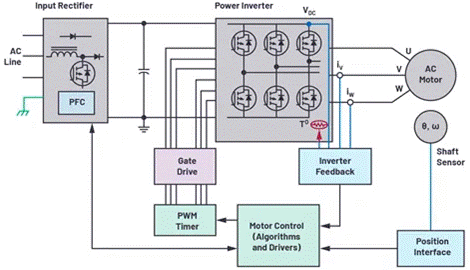
The motor control loop (shown in Figure 1) mainly consists of the motor, controller and position feedback interface. The motor turns the rotating shaft and drives the robotic arm to follow. The motor controller controls when the motor applies force, stops, or continues to turn. The position interface in the loop provides speed and position information to the controller. For the assembly machine that assembles the micro-surface PCB, this data is the key to its normal operation. These applications all need to obtain accurate position measurement information about rotating objects. The resolution of the position sensor must be very high enough to accurately detect the position of the motor shaft, pick up the corresponding micro component, and place the component in the corresponding position on the board. In addition, the higher the motor speed, the higher the loop bandwidth required and the lower the delay.
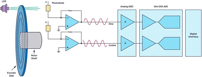
In low-end applications, the use of incremental sensors and comparators may be able to implement position detection, but in high-end applications, more complex signal chains are required. These feedback systems consist of position sensors, followed by analog front-end signal conditioning, ADCs, and ADC drivers through which data passes before entering the digital domain. One of the most accurate position sensors is the optical encoder. The optical encoder consists of an LED light source, a marking disc connected to the motor shaft, and a photodetector. The disc contains opaque and transparent mask areas that block or let light through. A photodetector detects these rays, and the on/off light signal is converted into an electronic signal. As the disk rotates, the photodetector (in conjunction with the disk's pattern) generates small sine and cosine signals (in the mV or µV class). This system is typical for absolute position optical encoders. These signals enter the analog signal conditioning circuit (typically consisting of a discrete amplifier or analog PGA to acquire signals in the peak-to-peak range up to 1 V), usually to match the ADC input voltage range to the maximum dynamic range. Each amplified sine and cosine signal is then captured by the driver amplifier of the synchronous sampling ADC. Each channel of the ADC must support synchronous sampling in order to obtain both sine and cosine data points, which in combination provide axis position information. The ADC conversion result is sent to the ASIC or microcontroller. The motor controller queries the encoder position during each PWM cycle and then uses this data to drive the motor according to the received instructions. In the past, system designers had to sacrifice ADC speed or channel count in order to integrate into limited board space.

Optimized position feedback
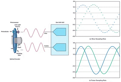
The continuous development of technology has led to continuous innovation in motor control applications requiring high-precision position detection. The resolution of the optical encoder may be determined by the number of slots on the disc for fine lithography, usually several hundred or several thousand. When these sine and cosine signals are inserted into a high-speed, high-performance ADC, a higher-resolution encoder can be created without system changes to the encoder disc. For example, when sampling the encoder's sine and cosine signals at a lower rate, only a few signal values will be captured, as shown in Figure 3. This limits the accuracy of the position capacitance. In Figure 3, when the ADC samples at a faster rate, more detailed signal values can be obtained, allowing for more precise location determination. The ADC's high sampling rate supports oversampling, further improving noise performance and eliminating some digital post-processing requirements. At the same time, the output data rate of the ADC can be reduced; That is, slower serial frequency signals are supported, thus simplifying the digital interface. The motor position feedback system is mounted on the motor assembly, which can be very small in some applications. Therefore, whether it can be loaded into the PCB area where the encoder module area is limited, size is the key. Integrating multiple channel components in a single micro package is very space-saving.

Optical encoder position feedback design example
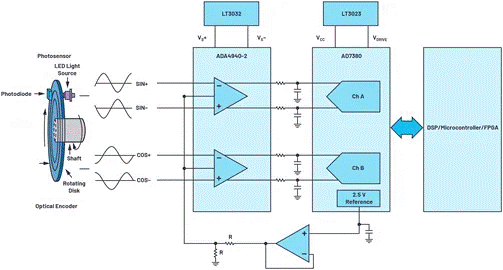
Figure 4 shows an example of an optimized solution for an optical encoder position feedback system. This circuit is easily connected to an absolute type optical encoder, and then the circuit easily captures the differential sine and cosine signals from the encoder. The ADA4940-2 front-end amplifier is a dual-channel, low-noise fully differential amplifier used to drive the AD7380, a dual-channel, 16-bit fully differential 4 MSPS synchronous sampling SAR ADC in a 3 mm × 3 mm small LFCSP package. The on-chip 2.5V reference voltage source allows this circuit to use a minimum number of components. The VCC and VDRIVE of the ADC, as well as the power track of the amplifier driver, can be powered by LDO regulators, such as the LT3023 and LT3032. When these reference designs are interconnected (for example, using a 1024-slot optical encoder that generates 1024 sine and cosine cycles in one encoder disc cycle), the 16-bit AD7380 samples in each encoder slot of 216 codes, increasing the overall resolution of the encoder to 26 bits. 4 MSPS throughput rate ensures that details of sine and cosine periods are captured, as well as the latest encoder position information. The high throughput rate enables on-chip oversampler, which reduces the time delay when a digital ASIC or microcontroller feeds the exact encoder position back to the motor. Another benefit of the AD7380 in-chip oversampling is the ability to add an additional 2-bit resolution, which can be used in conjunction with in-chip resolution enhancement. Resolution enhancements can further improve accuracy, up to 28 bits.

conclusion
Motor control systems require higher precision, higher speed, and a higher degree of miniaturization, and optical encoders are used as motor position detection devices. Therefore, when measuring the position of the motor, the optical encoder signal chain must have high precision. The high speed, high throughput ADC accurately captures information and then sends motor position data to the controller. The speed, density and performance of the AD7380 meet industry requirements while achieving greater accuracy and system optimization in position feedback systems.
免责声明: 本文章转自其它平台,并不代表本站观点及立场。若有侵权或异议,请联系我们删除。谢谢! Disclaimer: This article is reproduced from other platforms and does not represent the views or positions of this website. If there is any infringement or objection, please contact us to delete it. thank you! |


