
intro
Oversampling and digital filtering help reduce the need for an anti-aliasing filter in front of the ADC. Reconstructed Dacs can apply the principles of oversampling and interpolation in a similar way. For example, digital audio CD players often use oversampling, where the basic data from the CD is updated at a rate of 44.1 kSPS. Early CD players used traditional binary Dacs and inserted "0" into parallel data, thereby increasing the effective update rate to 4, 8, or 16 times the base throughput rate. 4×, 8×, or 16× data flows through a digital interpolation filter, producing additional data points. The high oversampling rate moves the image frequency to a higher position, allowing simpler, lower cost filters with wider transition bands to be used. In addition, the SNR within the signal bandwidth is also increased due to the presence of processing gain. The Delta-Sigma DAC architecture extends this principle to the extreme by using a much higher oversampling rate, making it popular in modern CD players.
The same principles of oversampling and interpolation can also be applied to high-speed Dacs in the field of communications, in order to reduce the requirements on the output filter and increase the SNR with the processing gain.
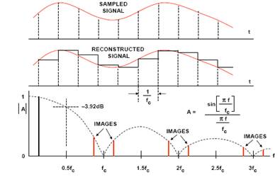
Reconstruct the DAC output spectrum
The output of the reconstructed DAC can be represented as a series of rectangular pulses with a width equal to the inverse of the clock rate, as shown in Figure 1.
Oversampled interpolation DAC
The basic principle of oversampling/interpolating DAC is shown in Figure 2. N-bit input data words are received at rate fc. The digital interpolation filter operates at a clock rate equal to the oversampling frequency Kfc and inserts additional data points. The effect on the output spectrum is shown in Figure 2. At the Nyquist sampling frequency (A), the requirements for an analog antimirror filter can be quite high. Through oversampling and interpolation, the requirements for this filter can be greatly reduced, as shown in (B). In addition, the quantization noise is distributed over an area with a wider bandwidth than the original signal, so the signal-to-noise ratio is also improved. When the original sampling rate is doubled (K = 2), SNR is increased by 3 dB. For K = 4, SNR increases by 6 dB. Early CD players took advantage of this and were generally able to refine the algorithms in digital filters to more than N bits. Today, most Dacs in CD players are of the Delta-Sigma type.
The earliest literature on the principle of oversampled/interpolated DAC is the 1974 paper by Ritchie, Candy, and Ninke (Ref. 1), and the patent filed by Mussman and Korte in 1981 (date of filing) (Ref. 2).
The AD9773/AD9775/AD9777(12-/14-/16-bit) series Transmitting Dacs (TxDAC®) are 2 x, 4 x, or 8 x selectionable oversampled interpolation dual-channel Dacs, for which a simplified block diagram is shown in Figure 4. These devices are capable of handling 12/14/16-bit input word rates of up to 160 MSPS and maximum output word rates of 400 MSPS. Assuming that the output frequency is 50 MHz, the input update rate is 160 MHz, and the oversampling ratio is 2, the image frequency appears at 320 MHz - 50 MHz = 270 MHz, so the transition band of the analog filter is 50 MHz to 270 MHz. If there is no 2x oversampling, the image frequency occurs at 160 MHz - 50 MHz = 110 MHz, and the filter transition band is 50 MHz to 110 MHz.
It should also be noted that the oversampled interpolation DAC supports a lower input clock rate and input data rate, so it is much less likely to generate noise within the system.
Σ-Δ typeDAC
The principle of operation of a sigma-δ DAC is very similar to that of a Sigma-δ ADC, but in a Sigma-δ DAC, the noise shaping function is implemented using a digital modulator rather than an analog modulator.
Unlike sigma-δ ADCs, Sigma-δ Dacs are mostly digital (see Figure 5A). It consists of an "interpolation filter" (a digital circuit that accepts data at a low rate, inserts 0 at a high rate, then applies the digital filter algorithm and outputs the data at a high rate), a Delta-type modulator (which is a low-pass filter for the signal and a high-pass filter for quantized noise, and converts the resulting data into a high-speed bitstream), and a 1-bit DAC. The DAC's output switches between the equivalent positive and negative reference voltages. The output is filtered in an external analog low-pass filter (LPF). Due to the high oversampling frequency, the complexity of the LPF is much lower than that of the traditional Nyquist sampling frequency.
In the past, multibit Dacs were difficult to design due to the precision requirements of an N-bit internal DAC (although it only has n bits, it must have the linearity of the final n bits). However, the AD195x series audio Dacs solve this problem by leveraging proprietary "data scrambling" technology known as "data directed scrambling" to deliver outstanding performance across all audio specifications.
Figure 6 shows the AD1955 multi-bit sigma-δ audio DAC. The AD1955 also uses data-directed scrambling technology, supports a variety of DVD audio formats, and has a very flexible serial port. The typical value of THD + N is 110 dB.
Sum up
In modern data sampling systems, oversampling combined with digital filtering is a powerful tool. We have seen that the same basic principle applies to both ADCs and refactoring Dacs. The main advantage is that the requirements for anti-aliasing/anti-mirroring filters are reduced, and another advantage is that the SNR is increased due to the processing gain.
The sigma-δ-type ADC and DAC architectures are terminal extensions of the oversampling principle and are the architecture of choice for most voice band and audio signal processing data converter applications.
免责声明: 本文章转自其它平台,并不代表本站观点及立场。若有侵权或异议,请联系我们删除。谢谢! Disclaimer: This article is reproduced from other platforms and does not represent the views or positions of this website. If there is any infringement or objection, please contact us to delete it. thank you! |

WeChat Official Account

WeChat Service
 Email
Email QQ
QQ 13823761625
