
Choosing the inductance value of the output filter for a Class D audio amplifier is always a key design decision. With the advent of a new generation of ultra-low distortion Class D amplifiers, choosing inductors with poor electrical performance can severely limit audio performance. In his December blog post, my colleague Brian talked about how high definition audio is changing the way we listen. In this blog post, I will discuss the important considerations for choosing the right inductor to ensure that your device is capable of high definition potential.
In higher power Class D amplifiers, (typically higher than 10W of output power), passive output filters usually have an inductor and a capacitor (LC) at each output, and are therefore referred to as LC filters. The purpose of the LC filter is to convert the discontinuous pulse width modulation (PWM) pulse train output of a Class D amplifier into a continuous and smooth analog sine wave. The LC filter extracts the audio signal from the PWM representation of the audio signal.
This filtering process is critical for several reasons:
(EMI) Reduces electromagnetic interference。The PWM output of a Class D amplifier is a high-amplitude voltage signal, usually equal to the output stage or PVDD supply voltage. Using an LC filter to filter out these pulses also filters out the high frequency capacity associated with PWM pulses, thereby reducing annoying EMI radiation. By placing the LC filter as close to the amplifier as possible, the long-term operation of the speaker will also not radiate EMI radiation throughout the system.
Reduce ripple current.For a Class D amplifier with an AD modulation scheme but no LC filter, there is a ripple current superimposed on the audio signal. With the LC filter, especially if the LC filter's cutoff frequency is reduced relative to the PWM switching frequency of the amplifier, the ripple current is also reduced, so that only a small amount of residual ripple will be present with the LC filter. The reactance of the LC filter filters out the rest of the ripple, ideally without consuming any power.
Let's use TPA3251D2 as an example. It is a 175W Class D audio amplifier with total harmonic distortion and noise (THD + N) up to 0.001% in the mid-power band. For the TPA3251D2, the linearity of the inductor becomes critical in extracting the highest level of audio performance.
For this discussion, inductance linearity is defined as inductance versus current.
An ideal inductance retains a specified inductance value regardless of the current passing through it. However, the inductance of a real-world sensor always decreases as the current increases. At some point, the current level will saturate the inductor, and the inductance will drop severely. This is usually designated as Isat.
Keep in mind that the inductance variation of the Isat rated current provided by different manufacturers is different, and even the inductance type is different. Some manufacturers specify Isat at 30% or more in the inductance. For LC Class D filters, if you expect this inductor to be rated at Isat all the time, you will observe very poor audio performance.
Table 1 shows the data collected from four different specifications of inductors with good linearity for high-performance Class D audio amplifiers. I measured the inductance at 1A current and again at 20A current (600 KHZ test signal), which is the nominal PWM switching frequency of the TPA3251D2 amplifier. Calculate the mean change in inductance for 10 samples of each inductor。
| manufacturer | A | A | B | B |
| Nominal inductance | 7mH | 10mH | 7mH | 7mH |
| 7mH average inductance change (10 samples, 1A-20A) | 0.94% | 1.38% | 1.16% | 1.55% |
In general, for a given core material, size, and geometry, the higher the inductance (the more turns the wire has), the worse the linearity of the inductor.
Next, I tested these inductors in the TPA3251D2 Evaluation module (EVM), and the results were clear, as shown in Figures 1 and 2.
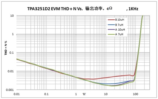
Figure 1: TPA3251D2EVM plot of measured inductor power (Watts) and THD + N output power
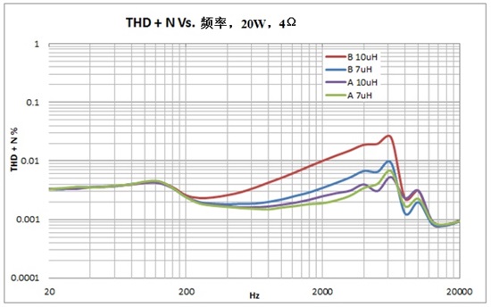
Also note that the total harmonic distortion and frequency performance are significantly improved at 20W. If you are designing an LC filter around an amplifier that accepts higher THD performance, or if the amplifier is inherently high in THD, manufacturer B's 10μH inductors can be a suitable candidate. At the end of the day, the designer of the system must choose between the inductor's linearity, cost, and size.
Other factors, such as switching loss or ohmic loss at high output power levels, will determine which inductor is best suited for a given system. However, by choosing an inductor with greater linearity, you can significantly improve the THD performance of your Class D amplifier, as evidenced by the ultra-low THD of the TPA3251D2.
If you've used a Class D amplifier before, please sign in and comment below. I would like to know more about which inductor you choose and the performance it produces.
免责声明: 本文章转自其它平台,并不代表本站观点及立场。若有侵权或异议,请联系我们删除。谢谢! Disclaimer: This article is reproduced from other platforms and does not represent the views or positions of this website. If there is any infringement or objection, please contact us to delete it. thank you! |

WeChat Official Account

WeChat Service
 Email
Email QQ
QQ 13823761625
