
Now more and more portable electronic products, home audio and video systems, car audio systems using class D amplifier, Class D amplifier with power saving, output power, good sound quality, signal stability and other characteristics, Li water Qing Mu Hua research report pointed out that by the audio player energy saving, thin and short demand to promote, Global Class D amplifier market sales will exceed $750 million in 2012. Even under the impact of the financial crisis, the demand for Class D audio amplifiers has not decreased.
EMI noise interference with surrounding equipment and circuits is completely unpredictable. Mobile phones have a large number of RF systems, such as calls, radio and other functions. Generally speaking, the relevant regulations are required for EMI. Printed circuit boards, clock circuits, oscillators, digital circuits, and processors become the internal EMI sources of the circuit. Some electromechanical devices that switch on and off current produce EMI during critical operations. These EMI signals do not necessarily have a negative effect on other electronic devices. The spectral composition and strength of the EMI signal determines whether it will have unexpected effects on sensitive circuits.
For Class D amplifiers, there are two main ways to reduce EMI:
1, for the sampling frequency of the power amplifier using spread spectrum technology, so that due to the sampling frequency caused by the EMI interference spectrum is relatively average, to achieve the purpose of reducing EMI.
2, control the opening and closing time of the output tube, and then control the EMI interference at the edge. It is generally believed that the second point is the main factor affecting the EMI of Class D power amplifier.
The spectrum component of a PWM signal is simplified to its frequency and rise time. The clock or system frequency establishes the time reference of the circuit, but its edge rate forms interfering harmonics. The energy of EMI mainly depends on the change time and the magnitude of the change. Electromagnetic interference (EMI) travels in two ways: conduction and radiation. That is, electromagnetic interference is divided into two types: conductive electromagnetic interference and radiant electromagnetic interference. When the frequency of electromagnetic interference wave is less than 30MHz, electromagnetic interference mainly generates conductive noise in electronic equipment by conducting mode. When the frequency of the electromagnetic interference wave is higher than 30MHz, the electromagnetic interference mainly produces radiation noise in the electronic equipment by radiation. The current common EMI standards are FCC and CISPR, which are mainly concerned with interference in the 30MHz band.
The relationship between the maximum frequency of EMI generation and the edge change time is shown below. For example, when the edge change time is 10ns, the calculated fmax=31.8MHz, that is to say, the system will be affected by the frequency within 31.8MHz.
Class D power amplifier also has disadvantages, when the output signal of Class D power amplifier is a high current and high speed pulse width modulation switch signal, the switch signal is transmitted by the horn line to the horn, indirectly causing electromagnetic radiation and electromagnetic interference (EMI). This EMI interference contains a wide spectrum, and different frequency bands interfere with different receivers, even interfering with non-receiver electronics.
The following are common solutions to EMI interference
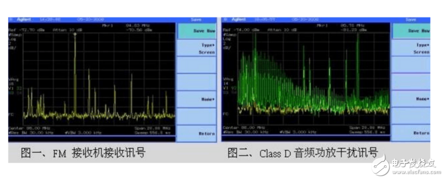
● Figure 1 is the received signal at the antenna end of the general FM receiver. When the class D power amplifier operates, if the harmonic signal radiated by it is not effectively processed, the result will be as shown in Figure 2, the harmonic signal covers the original FM signal, so that the FM reception quality is reduced, or even cannot be received
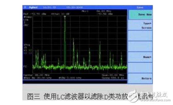
The EMI interference problem can be started from two aspects: radiation and conduction. The selection of PCB Layout and LC filter to block radiation interference is an effective direction. The quality of FM receiving can be improved effectively by adjusting the combination of output LC filter according to the frequency band of D power amplifier radiation. Figure 3: The interference phenomenon in the original figure 2, after suitable LC filter processing, can eliminate the interference problem of Class D power amplifier.
The conducted emission through the power supply/ground wire is also another source of interference, in addition to the isolation on the PCB Layout, the coupling filter is the choice.
● Reducing the strength of the interference signal can also be done. The main thing is to change the frequency of interference. Shortening the horn line of a Class D amplifier can reduce the emission efficiency of the antenna (horn line) to reduce the intensity of interfering radiation waves.
The method of reducing the intensity of interference radiation wave is to Filter the switching signal of Class D power amplifier using an inductance capacitor filter (LC Filter) and take out its audio signal, and then transmit it to the speaker through the speaker wire. In this way, the transmission signal of the horn line is an audio signal and the high-frequency switching signal has been greatly attenuated. Because the length of the horn line of the Class D amplifier is relatively short in the application of portable electronic products, magnetic beads can be used for some particularly high harmonic filtering, without the use of LC Filter to achieve the effect.
Another way to reduce the interference signal is to use the spread frequency technique. The way to spread the frequency is to change the high frequency carrier frequency of the Class D amplifier over time, so that the interference signal is distributed in several frequency regions rather than all concentrated in one frequency region. If the high-frequency carrier frequencies are rotated at an average of 10 frequencies, EMI can theoretically be reduced by 10db.
● The use of frequency hopping methods can also effectively avoid interference. If the receiver is a class D amplifier when receiving a certain frequency
If the high frequency switching signal is interfered with, the high frequency switching frequency of Class D power amplifier can be jumped to another frequency. Since the audio content of the Class D amplifier is independent of its carrier or switching frequency, this method does not affect the content of the audio signal. As long as this switching frequency is not in the range of the Bandpass Filter of the receiver, the receiver can effectively suppress the interference signal.
● The way to solve the interference of FM in the street is to use a metal shell shield to attenuate the interference energy of harmonic radiation, and then make the FM receive normally. However, when the FM receiver is combined with the Class D power amplifier, this shielding method is not applicable, and it is necessary to start from the EMI prevention of the class D power amplifier.
免责声明: 本文章转自其它平台,并不代表本站观点及立场。若有侵权或异议,请联系我们删除。谢谢! Disclaimer: This article is reproduced from other platforms and does not represent the views or positions of this website. If there is any infringement or objection, please contact us to delete it. thank you! |

WeChat Official Account

WeChat Service
 Email
Email QQ
QQ 13823761625
