
I2S is only a branch of PCM, the interface definition is the same, I2S sampling frequency is generally 44.1KHZ and 48KHZ, PCM sampling frequency is generally 8K,16K. There are four sets of signals: the bit clock signal, the synchronization signal, the data input, and the data output.
| I2S bus standard number, data input, data output. |
Serial clock SCLK, also known as the bit clock BCLK, that corresponds to every bit of digital audio data, SCLK frequency =2× sampling frequency × sampling bits, ha ha, now the question comes, some people will ask what these things mean? In fact, I2S is generally transmitted stereo sound, there are two channels, sampling frequency refers to the sampling rate, how long to collect a point, each point is composed of several bits.
The frame clock LRCK is used to switch the data of the left and right channels. An LRCK value of 0 indicates that the data of the left channel is being transmitted, and an LRCK value of 1 indicates that the data of the right channel is being transmitted. LRCLK == FS, which is the sampling frequency
Serial data SDATA is audio data represented by binary complement, and sometimes in order to enable better synchronization between systems, it is necessary to transmit another signal MCLK, called the master Clock, also known as the System Clock, which is 256 or 384 times the sampling frequency
| I2S Protocol timing |
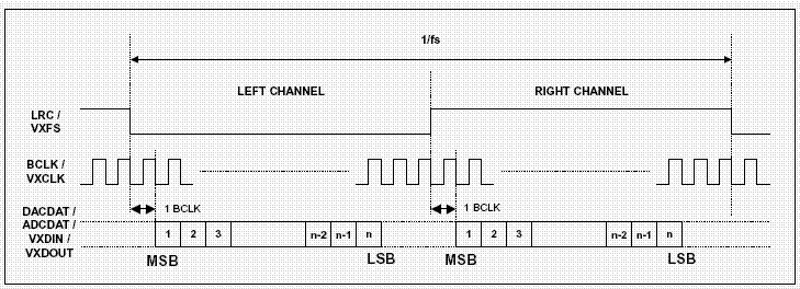
It can be seen from the time sequence diagram that the sound channels around I2S are respectively high and low levels, and PCM has only one starting signal, and the data of the left channel closely follows that of the right channel.
| PCM protocol |
PCM (PCM-clock, PCM-sync, PCM-in, PCM-out) pulse code modulation, analog voice signal after sampling quantization and certain data arrangement is PCM. Theoretically, it can transmit mono, two-channel stereo and multi-channel sound. It's raw data for digital audio.
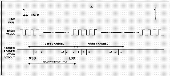
It can be seen from the time sequence diagram that the sound channels around I2S are respectively high and low levels, and PCM has only one starting signal, and the data of the left channel closely follows that of the right channel.
| It can be seen from the time sequence diagram that the sound channels around I2S are respectively high and low levels, and PCM has only one starting signal, and the data of the left channel closely follows that of the right channel. |
免责声明: 本文章转自其它平台,并不代表本站观点及立场。若有侵权或异议,请联系我们删除。谢谢! Disclaimer: This article is reproduced from other platforms and does not represent the views or positions of this website. If there is any infringement or objection, please contact us to delete it. thank you! |

WeChat Official Account

WeChat Service
 Email
Email QQ
QQ 13823761625
