You learned how missing code in an ADC can lead to distorted ADC output. This distortion causes harmonics of the input signal to appear in the output of the ADC. While ADCs with missing codes do produce a lot of harmonic distortion, missing codes are not the source of harmonic distortion. Harmonic distortion in the ADC output is caused by any nonlinearity present in the ADC characteristics. Every practical ADC has nonlinear characteristics. Therefore, harmonics are present in the output of every real ADC. DNL and INL are measures of the nonlinearity of the ADC characteristics, while THD is a measure of the harmonic distortion generated in the ADC output.

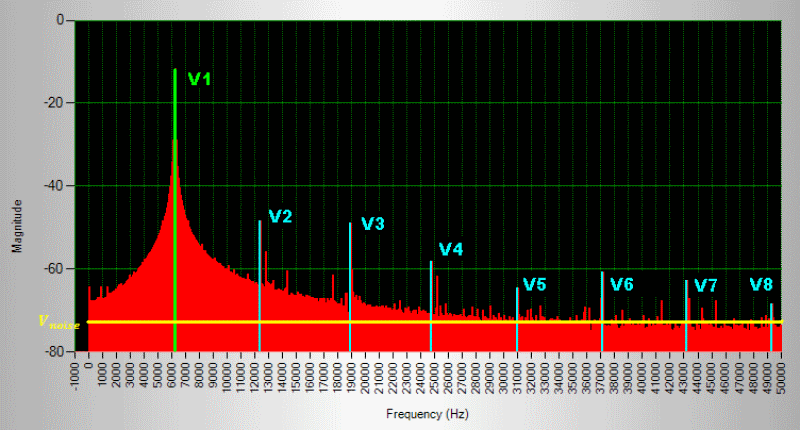
To visualize harmonic distortion in the ADC output, we will provide a sine wave as the input to the ADC and plot the Fourier transform (aka FFT) of the ADC's digital output. Figure 1 shows an example of the FFT output from such an ADC. Ideally, the FFT should have a single frequency spike at the sine wave frequency. Although the frequency of the input signal has an amplitude in the FFT plot (the green stem in the FFT), other frequency content can be seen in the plot. The input signal frequency is called the fundamental frequency. In addition to the fundamental frequency component, spikes (blue stems) occur periodically in the FFT. These are harmonics of the input signal frequency.
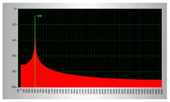
The ADC used for measurement in Figure 1 has considerable nonlinear characteristics. For good ADC design, the output FFT of the ADC will look much cleaner. Figure 1-1 below shows an example of this. We need more tools and measuring equipment to characterize the distortion of such ADCs.

Total harmonic distortion is defined as the power of the harmonic content in the ADC output relative to the fundamental frequency power. It can be expressed in decibels or percentages according to equations (1) and (2), respectively.

As shown in Figure 1, when we move to the higher harmonics of the ADC, the amplitude of the harmonics (and therefore the power of the harmonic frequency) generally decreases. Therefore, when calculating the total harmonic distortion, only the first few harmonics are taken into account. The ADC data table should specify the number of harmonics considered when calculating the total harmonic distortion number in the data table.
In addition to the fundamental and harmonic frequency components of the ADC, Figure 1 also shows the presence of some power at every other frequency component (marked in red). This corresponds to the noise present in the ADC output.
免责声明: 本文章转自其它平台,并不代表本站观点及立场。若有侵权或异议,请联系我们删除。谢谢! Disclaimer: This article is reproduced from other platforms and does not represent the views or positions of this website. If there is any infringement or objection, please contact us to delete it. thank you! |


