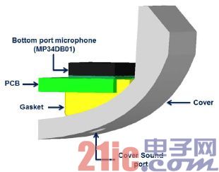
Below is a typical tablet microphone sound path:
Helmholtz resonance
The structure composed of narrow acoustic holes connected with hollow chambers will produce acoustic resonance when stimulated by sound waves. This resonance occurs when we blow air above the mouth of an empty bottle. The structure is called the Helmholtz resonator, named after Hermann von Helmholtz, the inventor of the phenomenon. Helmholtz uses resonators with different resonant frequencies to identify the frequency components of complex sounds such as music.
The center frequency of the Helmholtz resonance is determined by the following program:

Where c is the air speed; AH is the cross-sectional area of the sound hole; LH is the length of the sound hole; VC is the volume of the cavity. The equation assumes that the resonator is a simple structure consisting of a cavity connected to a pipe of equal cross section. If the cross-sectional area and material of the sound path of the microphone are different, the equation describing the acoustic characteristics of the sound path is much more complex. Therefore, it is necessary to simulate the acoustic characteristics of the whole sound path to accurately predict the overall performance of the acoustic design.
In this paper, by changing the thickness and inner diameter of the microphone seal ring, the diameter of the sound hole of the product housing, the diameter of the sound hole of the printed circuit board, the bending of the sound path and the acoustic impedance of the path material, we carry out the frequency response simulation experiments on different sound paths. The experimental results allow designers to predict in advance the extent to which changes in these parameters will affect the overall performance of the sound path.
The frequency response of the microphone
The low frequency of the MEMS microphone is determined by the following main parameters: the size of the ventilation hole between the front and back of the sensor diaphragm; Volume of the posterior chamber. The high frequency of MEMS microphones is determined by the Helmholtz resonance generated by the sound hole in the front chamber of the microphone.
For most MEMS microphones, when the sensitivity of the microphone drops to low frequency and then rises to high frequency, the frequency response curve is roughly the same because of the Helmholtz resonance. However, different MEMS mics differ greatly in sensor design, package size and structure, so the overall frequency response, especially the high frequency response, varies greatly. Most of ST's microphones place the sensor directly above the sound hole to minimize front chamber volume and ensure excellent high frequency response.

The following simulation results describe the frequency response of the ST MP34DB01 MEMS microphone itself. The simulation tool solves the equation at each discrete point of the sound path model, and at the end of the simulation, plots the data collected at all useful points.
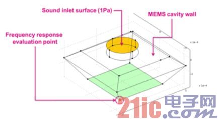
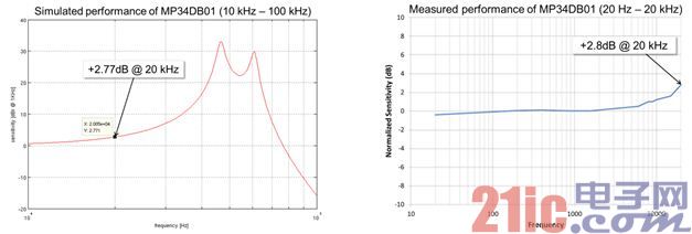
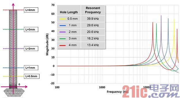
The microphone sealing ring plays an airtight role between the microphone sound hole and the product housing sound hole. After a microphone seal is installed, the length from the sound hole to the microphone front chamber is extended, resulting in a change in frequency response. In the following simulation experiment, round tubes of different lengths but with a fixed diameter (400μm) are placed on the microphone hole to evaluate the extent to which the sealing thickness affects the frequency response.
Effect of inner diameter of sealing ring on frequency response
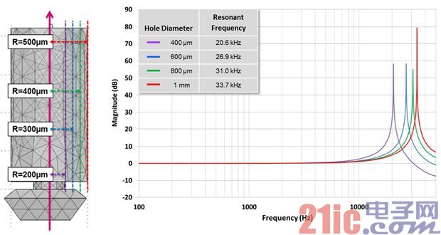
The next simulation experiment was to evaluate the effect of seals with different inner diameters but fixed thickness (2mm) on frequency response. FIG. 6 shows the simulation results of seals with different inner diameters.
The influence of sound path shape on frequency response
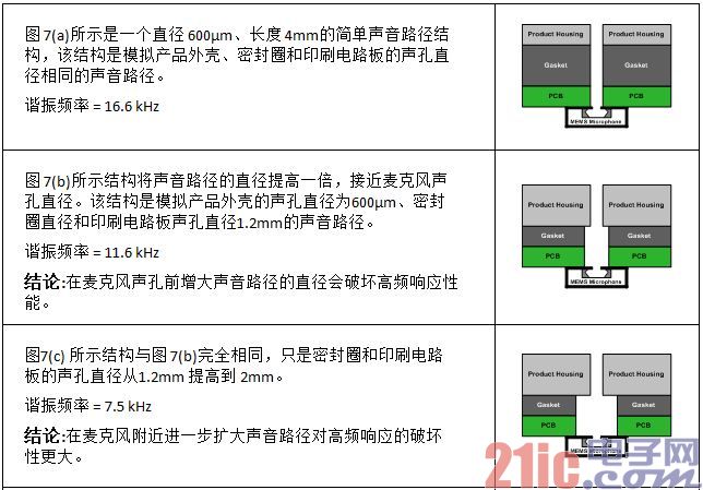
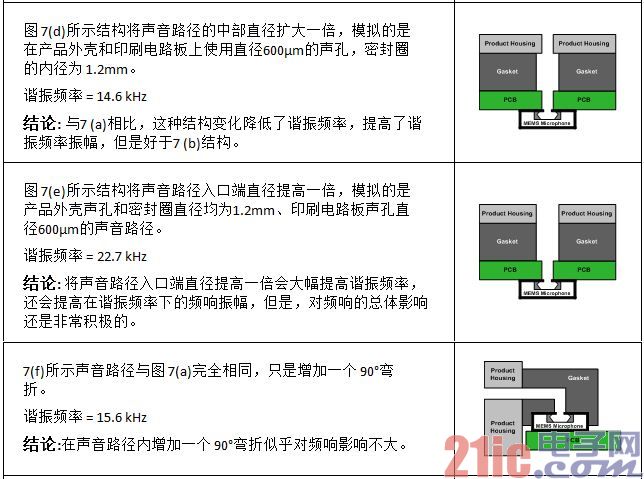
So far, the simulation results are consistent with the predicted results obtained by solving the Helmholtz resonance equation. The following simulation experiment discusses the influence of sound path shape changes on frequency response, which is difficult to predict. The structure shown in Figure 7(a) is a simple sound path with a length of 4mm and a diameter of 600μm, and other simulation experiments are based on this simple structure. In order to simulate changes in the width and shape of sealing rings, product housing sound holes and printed circuit board sound holes, the simulation experiment adds different lengths, radii and shapes of the cavity, and the sound path becomes very complicated.

图 7 – 声音路径形状变化
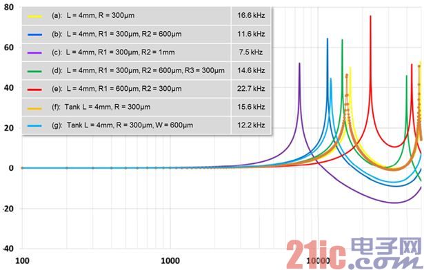
Figure 8 - Frequency response of MP34DB01 at different sound path shapes

The effect of sealing ring material on frequency response
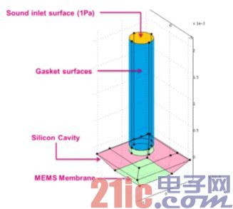
图 9 – 声音路径表面
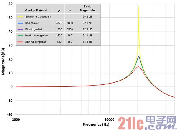
Figure 10 - Effect of seal material on resonance peak amplitude
Case study - Analyze the entire sound path of the sound hole mike under the tablet
Figure 11 shows the sound path of a tablet's lower sound hole mike. In this example, the lower sound hole is mounted on a printed circuit board, and an airtight soft rubber seal is inserted between the printed circuit board and the product housing.
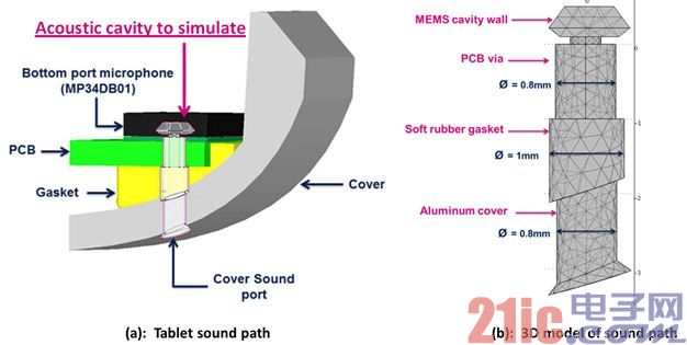
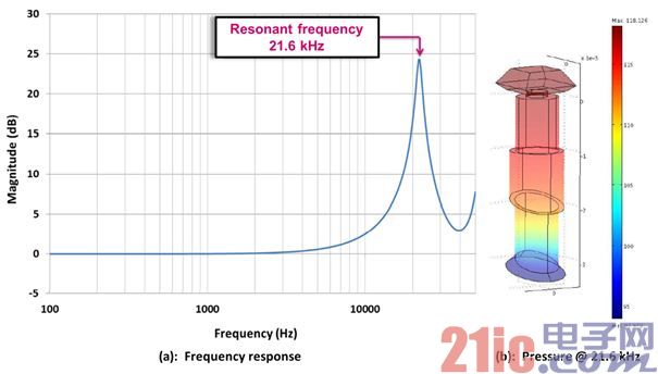
FIG. 12(a) shows the frequency response curve of a sound path with a resonant peak frequency of about 21.6 kHz, and FIG. 12(b) shows the distribution of air pressure in the sound path at a resonant frequency of 21.6 kHz. At this resonant frequency, the MEMS diaphragm is subjected to the greatest pressure.
The following guidelines help to optimize the frequency response of the microphone sound path.
● The shortest and widest sound path possible. Widening the external entrance of the sound path helps improve the frequency response, while widening the microphone end of the sound path reduces the frequency response performance.
● Try not to have any cavities in the sound path. If you can't avoid it, try to keep the cavity away from the mike hole.
● Sound path curvature seems to have little effect on frequency response.
● Soft sealing ring material can weaken resonance and improve frequency response performance.
免责声明: 本文章转自其它平台,并不代表本站观点及立场。若有侵权或异议,请联系我们删除。谢谢! Disclaimer: This article is reproduced from other platforms and does not represent the views or positions of this website. If there is any infringement or objection, please contact us to delete it. thank you! |


