A typical voltage-frequency converter is also called a VCO (voltage-controlled oscillator), in which the input voltage of the IC has a simple adjustment characteristic to the output frequency. Its general form is F=kV/RC, where RC is the time constant of the relative timing resistance and capacitance. These devices have a wide range of output frequencies, but few are capable of tuning over the entire interval of a set of RC time constants. However, if the timing ratio is changed as the input voltage changes, an implementation method can be used to amplify the tuning interval to almost the entire frequency range.
One way to achieve this goal is to replace the timing capacitor with a variable capacitor whose value can be reversed with its bias, which is the varactor diode. For this design, consider the AD654 voltage-to-frequency converter from ADI because it is simple and has a bandwidth of at least 1MHz.
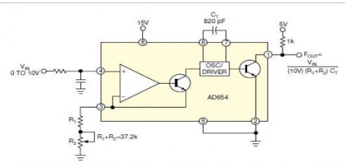
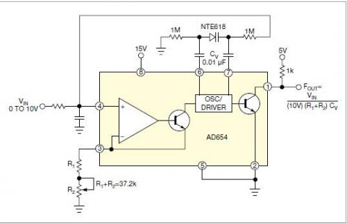
Figure 1 shows a typical implementation using a fixed resistor and capacitor. For the values in the figure, when the input changes from 0V to 10V, the frequency range is approximately 10Hz to 30kHz. After replacing the timing capacitor with the NTE618 hypermutation varactor (as shown in Figure 2), the same input range of 0V~10V can obtain a tuning interval of about 10Hz~1MHz.


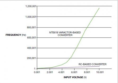
Figure 3 compares the tuning curves of the two converter structures. There is a considerable increase in the range of attention, but at the cost of linearity, in addition to affecting temperature stability. In short, precision is exchanged for tuning range, which should be acceptable in basic applications, since no special precision is required at this time.

Supermutation varactor can obtain large frequency changes with a small bias change because it has a large capacitance ratio. For some hypermutant varactor, the ratio can be as high as 15; for example, NTE618 is a hypermutant varactor used by an AM receiver. Since the converter frequency increases at higher voltages, the capacitance decreases, thus increasing the frequency. This combination of responses results in a wide tuning range. The 0.01μF coupling capacitor isolates the bias voltage of the varactor from the operating voltage of the converter core. A slight bias of the varator with a large resistance value of 1MΩ can avoid increasing the load on the oscillator.
This property is somewhat computable and predictable, even from a data table. The tuning curve of the varactor diode can be generated in Microsoft Excel. This information is then used in the voltage-frequency conversion equation for this converter. For NTE618, the approximate relationship between capacitance and voltage is expressed as:
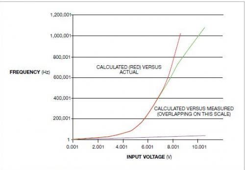
Figure 4 shows the similarity between the calculated and measured values. The difference is greater at higher frequencies because the capacitance of the varac diode is reduced to the order of the circuit and device stray capacitance. Careful wiring can minimize this problem and increase the range.

免责声明: 本文章转自其它平台,并不代表本站观点及立场。若有侵权或异议,请联系我们删除。谢谢! Disclaimer: This article is reproduced from other platforms and does not represent the views or positions of this website. If there is any infringement or objection, please contact us to delete it. thank you! |


