The answer is yes, at certain times and under certain conditions.
Many standard AC-DC switching power supplies specify a higher DC input range outside the most commonly used AC input range of 90-264VAC. We get a lot of questions about connecting the DC input to an AC-DC power supply that works with both AC and DC inputs, how to connect, where to connect, etc.
Where and why is HVDC power used? It turns out that many power stations provide high voltage direct current instead of the usual 115VAC or 208VAC grid to power the plant's equipment. This high voltage DC (typically 120 or 130-330VDC) can be easily combined with the battery to ensure power supply without the need for expensive centralized systems or local upinterruptible power supply systems.
Now back to the subject. Many switching power supply topologies can actually operate under AC or DC input conditions. Important: Please consult the application manual or specification details of the power supply to confirm that the power supply is designed to operate with AC or DC input.

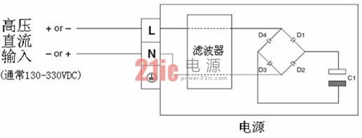
See the schematic diagram of the power supply below:
When powered by an AC sine wave, the current flows through the input filter during the first half cycle and is charged by diodes D1 and D3 to the capacitor C1. In the second half cycle (negative input), the current flows through the neutral end and through the diodes D2 and D4 to charge the capacitor C1.
When powered by high voltage direct current, the polarity of the connection is not critical to the operation of the power supply. If a positive input is connected at the firewire end, C1 is charged via diodes D1 and D3. If a positive input is connected at the neutral end, C1 is charged via diodes D2 and D4.
An important note here relates to the protective fusing of the power supply. Most power supplies have an AC quick-fuse type fuse in series with the input. It is recommended that the DC fuse be installed outside the power supply. If one end of the HVDC bus is grounded, the location of the fuse is usually in series with the high potential side (the ungrounded end). You are advised to consult local safety engineers for confirmation.


