Disclaimer: This article is transferred from other platforms and does not represent the views and positions of this site. If there is any infringement or objection, please contact us to delete it. thank you! |
Design of EMI filter for D-class power amplifier
Author: ShenZhen ChipSourceTek Technology Co.,Ltd. Browse: 56673 Publication Time: January 25, 2018
D-class amplifier output
The output of a Class D amplifier is PWM, and because the speaker itself is a filter, it can directly obtain analog signals without a filter. The following diagram shows the model circuit parasitic on the horn end:
The most commonly used 4 ohm parasitic inductance with an internal parasitic inductance of approximately 33UH: The simulated Bode plot is shown in the following figure:
It can be seen that just right -3DB falls at 19.5Khz, which perfectly meets the requirements for signal filtering.
Design of EMI certification with filter
D-class amplifiers generally have EMI problems because they output PWM waveforms, which can cause EMI to exceed the standard. There are two aspects to EMI exceeding the standard: one is the PWM path, and the other is that there may still be some high-frequency disturbances loaded on the signal after filtering by the speaker parasitic filter.
From the above summary, EMI certification requires the addition of filters or magnetic beads, and the placement should be close to the output pin of the D-class amplifier to avoid interference caused by excessively long PWM wiring.
Magnetic beads: exhibit resistance when passing through high frequencies. There are three important specifications for magnetic beads: frequency, impedance, and current. What is the effect of impedance in ohms on frequencies above or at this frequency.
LC filter: The most important factors are the cutoff frequency and Q value.
Cut off frequency: i.e. -3db point, approximately 0.707

LC first-order filtering with inductance=10UH and capacitance=1uf:

Q value: loss/input power. When the input power is fixed, the larger the Q value, the greater the loss and the greater the heat generation.
When the Q value is greater than 0.707, a peak appears in the curve. The larger the Q value, the larger the peak and the greater the fluctuation. The faster the decay rate of each octave of the decrease, the higher the THD of that frequency at the peak.
When the Q value is less than 0.707, the bandwidth of the entire curve narrows, causing a significant decrease in the original passband and affecting the sound.
So for EMI filters, in order to ensure that the frequency response of 20Hz-20kHz does not change, the Q value is best around 0.707, not too small or too large.

When the load is 4 ohms, the capacitance is 1UF, and the inductance is 10UH:

The simulated circuit is as follows:

The waveform of the simulated Bode plot is as follows:

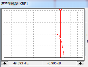
The calculated frequency is 51.7Khz, where -3db becomes 44.57HZ. This is because the Q value is less than 0.707, and the Q value of 0.632 is -3.98DB. The following figure shows the Bode plot of -3.9db, which corresponds to the calculated frequency. A Q value less than 0.707 reduces the original bandwidth, so the smaller the Q value, the narrower the bandwidth.

(The specific parameters are defined based on the actual component values. The ideal values for theoretical calculations do not exist in practice, so it depends on the actual situation to define the specific values. This parameter, combined with errors, may have more or less attenuation effects on high frequencies, but this attenuation is around 19KHZ, and the general human ear cannot distinguish the sound size at this frequency.)


