Source: Wolfspeed Author: Wolfspeed
intro
This white paper highlights Wolfspeed's 4th generation silicon carbide (SiC) MOSFET technology specifically designed for high power electronics applications. Building on its heritage in silicon carbide innovation, Wolfspeed regularly introduces cutting-edge technology solutions that redefine industry benchmarks. Prior to the release of Gen 4, Gen 3 silicon carbide MOSFETs have been proven in a wide range of use cases with a balance of several important design elements, setting the benchmark for comprehensive performance in hard switching applications.
While some vendors in the market focus only on specific factors of quality (FOM), such as conduction loss, RDS(on) at room temperature, or RDS(ON) × Qg, Wolfspeed takes a much broader and integrated approach. By simultaneously optimizing on-loss, switching performance, stability and reliability, Wolfspeed's design concept ensures performance across the board. The 4th generation MOSFETs continue this design philosophy, improving all metrics across the board, simplifying system design and improving ease of use while maintaining the ruggedized durability that Wolfspeed prides itself on.
The 4th generation MOSFETs are aimed at high-power automotive, industrial and renewable energy systems, bringing a new paradigm to silicon carbide technology. These devices provide a flexible basis for a long-term roadmap for product development, including application-optimized bare chips, modules, and discrete products. Each design based on Generation 4 technology focuses on three performance vectors: overall system efficiency; Excellent durability; Lower system cost. All of these features are designed to help designers achieve unprecedented performance and value.
Performance efficiency improvement
The importance of conduction loss
Minimizing on-off losses is critical for critical applications such as traction inverters in electric vehicles (EVs), industrial motor drives, and artificial intelligence (AI) server power supplies. These systems operate over a wide load range and typically operate at low power levels for extended periods of time. Reducing on-off losses increases efficiency across the load range, resulting in longer EV range, improved efficiency ratings for HVAC systems, and savings in cooling costs for server clusters due to reduced cooling requirements.
In addition, lower on-off losses can optimize the use of semiconductor materials, increase the power level of a given application or reduce its material cost, while achieving both efficiency and cost benefits.
Hard switch application
In hard-switching applications such as industrial motor drivers, AI data center power supplies, and active Front end (AFE) converters for grid-connected systems, reducing switching losses is critical.
Such applications run under different loads. They sometimes operate at very high power for short periods of time, but at lower power levels for most of their service life. From an efficiency perspective, minimizing on-off losses helps improve efficiency across the load range. In electric vehicles, for example, this means that the same battery can achieve a longer range or endurance.
Reducing switching losses has two major advantages. First, customers can increase the switching frequency, resulting in smaller, lighter, and more cost-effective magnetic components and capacitors. Second, customers can also prioritize efficiency gains by reducing heat dissipation and reduce system-level costs by using smaller radiators or lower cooling requirements. The above advantages are not mutually exclusive, and customers have the flexibility to optimize the design according to their specific needs.
* Read the application instructions to learn more about measuring switch and on-off losses.
In the 3-stage DC fast charger shown in Figure 1, AFE connects the converter to the grid. It converts the grid voltage into a stable DC link voltage that is used to charge the battery. Compared to larger, less efficient IGBTs, silicon carbide discrete devices and power modules reduce losses and increase efficiency because they are able to operate at higher frequencies and temperatures while reducing heat dissipation requirements.

Performance comparison between the 3rd generation MOSFETs and the 4th generation MOSFETs
In all power electronics applications, whether hard or soft switching, it is important to minimize on-off losses. The on-loss is primarily determined by the on-resistance (RDS(on)) of the power MOSFET, which is related to the current level required for the application and the resulting junction temperature. At full rated load current, the MOSFETs usually operate at temperatures close to their highest rated operating temperature (or slightly lower due to design margin). The MOSFET model selection and final system semiconductor BOM cost are determined by this high temperature RDS(on). The on-resistance of Wolfspeed's 4th generation MOSFETs can be reduced by up to 21% at high temperatures, and the reduction is even greater at lower temperatures. At light loads with low current levels and junction temperatures, RDS(on) directly increases system efficiency and prolongs operating life as the temperature decreases.
To illustrate the improvements in switching loss and ease of use of the 4th generation MOSFETs, the waveform of the half-bridge switching event should be considered. Building on the outstanding performance and reliability of the third-generation device, Wolfspeed's fourth-generation MOSFETs have improved switching speed and reduced voltage overshoot, thanks to improved diode performance and optimized design. These improvements in Gen 4 devices build on the strong foundation of Gen 3 and ensure consistent excellence during portfolio transitions, even in demanding applications.
Figures 2 and 3 show the dynamic switching performance of a 1200 V Generation 4 device compared to a generation 3 equivalent device. Adjust the grid resistance to provide a matched di/dt during on-off and a matched dv/dt during off. Fourth-generation devices enable faster switching speeds, and only a conservative method of comparing device performance is shown here.
During the on-off process, the body diode of the other MOSFET reverses and turns off, causing the reverse recovery current to flow through the body diode into the on-off MOSFET. The improved fourth-generation diode behavior is very evident in the conduction current waveform, and its current recovery is faster, which significantly reduces the on-off loss. In addition, the software diode performance of Generation 4 devices results in reduced ringing during switching action, which reduces system noise and improves EMI performance. The turn-off performance of the two generations of devices is similar, enabling low loss and low EMI.
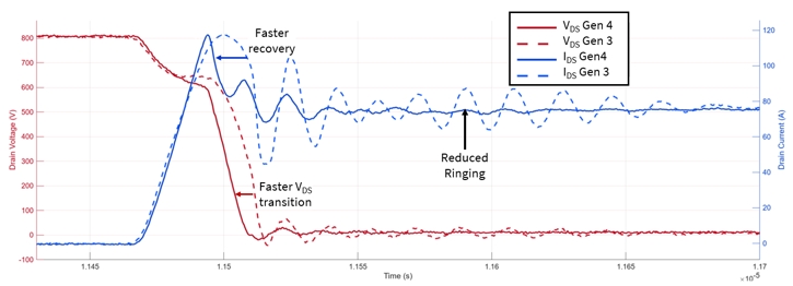
Figure 2: Comparison of conduction waveforms of 3rd and 4th generation MOSFETs
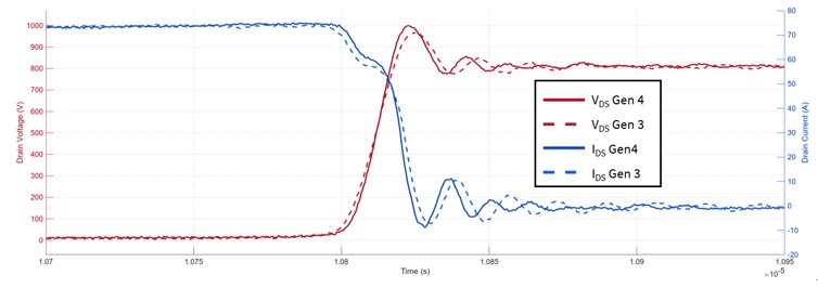
Figure 3: Comparison of turn-off waveforms of the 3rd and 4th generation MOSFETs
Figure 4 shows the loss between Wolfspeed's 3rd generation 21 mΩ MOSFETs and the 4th generation 25 mΩ devices. When matched with di/dt on and dV/dt off, a 27% reduction in ESW at rated current can be achieved. Some 4th generation MOSFETs can further improve switching losses by adopting lower Rg values.
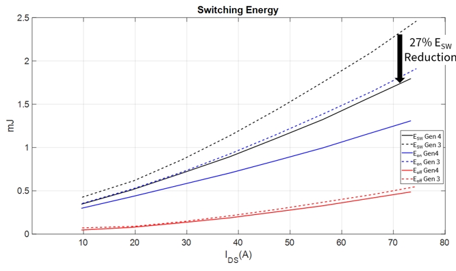
Generation 4 technology improves performance in hard switching applications, reducing EON and EOFF by up to 15%, while also reducing on-off losses in soft and hard switching applications and reducing RSP at operating temperatures by up to 21% (RDS(on) at 175 °C performs well).
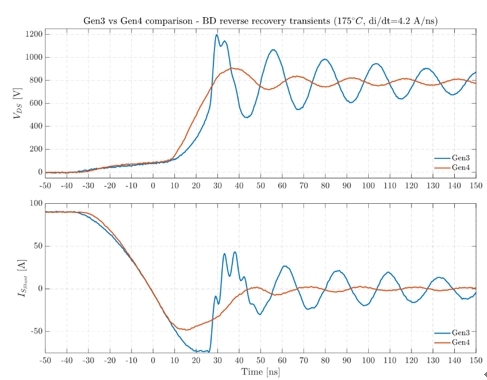
As can be seen from the comparison in Figure 2, another advantage of the 4th generation MOSFETs is the reduction of oscillations and ringing after reverse recovery. Compared to Generation 3, the waveform of Generation 4 MOSFETs is smoother, minimizing common mode voltage and radiation emission, and simplifying electromagnetic interference (EMI) filter design.
Reducing waveform noise simplifies the development of systems that require high-speed switching while addressing EMI challenges. For customers upgrading from Generation 3, Generation 4 provides a convenient upgrade path with significant improvements in waveform behavior and system design flexibility.
Cosmic ray reliability
High-altitude applications, such as electric vehicles or airplanes traveling in mountainous areas, face the risk of single-particle burnout caused by cosmic rays. These events are caused by the neutron flux (the number of neutrons hitting the semiconductor per unit time), which can produce drain-source currents (IDS), which in turn can cause adverse consequences.
The 4th generation MOSFETs feature an enhanced immunity design that reduces the cosmic ray failure rate (FIT) by a factor of 100 compared to previous generations. This increased reliability reduces the need for excessive voltage derating, making system design more efficient. In addition, they are able to withstand overload and overstress events. The Wolfspeed chip portfolio is certified for continuous operation at 185 °C and limited lifetime operation at 200 °C.
Short-circuit tolerance time is a key parameter for motor drives and traction systems, ensuring safe shutdown in the event of a failure. The 4th-generation technology supports endurance times of up to 2.3 microseconds and is compatible with existing gate driver technologies without compromising RDS(on) performance. The 4th generation MOSFETs are robust and efficient, making them ideal for demanding applications.
These features extend the Secure Workspace (SOA) to ensure robust performance. Designers can design with less semiconductor use, thereby reducing costs without compromising safety.
Soft-switch applications, such as UHF DC-DC converters for on-board chargers and the second stage of industrial power supplies, are designed differently from hard-switch front ends. Switching losses are minimized or even eliminated in such applications, so the on-off loss becomes the main residual loss. Typically, the front end has an active power factor correction (PFC) phase with a hard switch, followed by a soft-switch DC-DC converter phase.
The converter stage usually adopts a topology such as LLC, CLLC, phase-shifted full bridge or dual active bridge. In such designs, switching losses are less important, although the components still have to withstand high di/dt and dv/dt stresses and handle high resonant circuit currents.
The main advantage of soft switching applications is the reduction of on-off losses due to RSP improvements. This reduction in on-off losses applies across the load curve and is particularly beneficial for applications with Energy efficiency requirements, such as the Energy Star standard. Many of these power supplies must meet regulations that require high efficiency at different load levels, for example, meeting the 80 Plus titanium grade energy efficiency level of the server power supply.
Wolfspeed's 4th generation silicon carbide MOSFETs offer significant advantages in terms of reduced system costs and accelerated development time. By boosting on-off and switching frequencies, these devices enable engineers to design systems with smaller, lighter, and less expensive components, such as heat sinks, EMI filters, and magnetic components.
Thanks to the excellent RSP performance, up to 30% power output can be achieved in the same area, thus increasing power density without adding additional space.
Enhanced robustness and reliability, including reduced sensitivity to environmental factors such as cosmic rays, enable designers to use a smaller safety margin, further minimizing the amount of semiconductor material required. In addition, the plug-and-play compatibility of the 4th generation MOSFETs allows existing users to easily upgrade, reducing the effort of redesign.
As shown in Figure 5, the fourth-generation device has a 3.5-fold increase in the body diode softness factor: MOSFETs effectively minimize EMI in reverse recovery scenarios, enabling smoother operation without the need for QRR trade-offs. Switching operation is safe and simple even at high dv/dt, thanks to a capacitance ratio of up to 600:1, which eliminates the risk of parasitic overshoot and ensures reliable system performance under harsh conditions. All of these improvements combined enable developers to achieve optimized system performance in a shorter design time while meeting stringent efficiency and reliability requirements.
Wolfspeed is always focused on customer needs and is committed to achieving system durability, efficiency and power density through packaging strategies. Advanced packaging further enhances the benefits of Generation 4 technology, enhancing thermal management and ensuring the durability of the device under harsh conditions such as power and temperature cycling.
Silicon carbide devices break the limits of traditional silicon-based power packages with their high switching speed and thermal performance. Conventional designs are often subject to parasitic inductance, resulting in voltage overshoot, oscillation, and gate oxide damage. These issues not only affect efficiency, but also require costly design trade-offs.
Advanced packaging technology tailored for silicon carbide minimizes parasitic inductance in power, gate, and common source loops, thereby increasing efficiency, reducing switching losses, and supporting the use of lower-rated silicon carbide devices. Features such as double-sided cooling and compact layout support high-power applications, thermal control and higher switching frequencies to realize the full potential of silicon carbide in reliable and energy efficient systems.
Minimizing inductance in the power module can reduce voltage oscillations, enabling concise switching operation and higher efficiency. Innovative technologies such as internal busbars and clamp attachments reduce inductance to the level of 5 Nahen, further reducing switching losses and improving system stability.
Innovative interconnection methods are essential to improve power module performance. Traditional lead-bonded packaging technologies are being replaced by advanced technologies such as top-clip-on interconnects that reduce resistance, improve thermal management, and enhance mechanical reliability. Copper clamps are welded or sintered directly to the chip to improve power flow and connection strength.
Silver sintering is a state-of-the-art chip bonding technology that creates a strong connection between the chip and a substrate such as silicon nitride, ensuring excellent thermal conductivity and mechanical durability. This method is increasingly used in applications that require high power and thermal cycling performance.
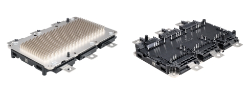
As power density increases, effective thermal management is critical. Direct cooling solutions, such as pin-fin designs in which the fins are immersed in the coolant (see Figure 4), can effectively help dissipate heat from the chip. These methods enable SIC devices to maintain high performance at high temperatures, especially in automotive systems.
Reliability is crucial for automotive power modules, which must meet stringent standards such as AEC-Q101 and AQG324. Advanced materials and processes address failure mechanisms such as moisture penetration and lead bond degradation. For example, epoxy resin molding compounds are replacing gel-based packaging materials, providing excellent moisture resistance and structural integrity. Enhanced crimp pin technology enables higher PCB connection current capacity for compact and high-power designs.
Key points and conclusions
The newly introduced 4th generation silicon carbide technology strikes a balance between on-loss, switching performance and durability, marking a significant step forward in power electronics. Unlike other vendors that focus on limited metrics such as RDS(on) at room temperature, Wolfspeed prioritizes maximizing in-circuit value under actual operating conditions. The new platform will lay the foundation for the long-term development of system-optimized power modules, discrete devices and bare chip products, and will benefit industries such as electric vehicles, industrial motor drives, AI server power supplies, renewable energy systems and avionics.
In electric vehicles, lower on-off losses extend battery range, while in industrial motor drives, higher efficiency reduces energy consumption and cooling costs.
In hard switching applications such as motor drivers and grid power converters, improved switching characteristics increase switching frequency or efficiency, thereby reducing system size and cost. Lower switching losses also simplify thermal management and support compact design. Enhanced reverse recovery reduces EMI and simplifies filter design and conformance testing, while also addressing reliability challenges such as single-particle burn-out caused by cosmic rays.
The 4th-generation MOSFETs have a short-circuit tolerance time of 2 microseconds to ensure safe operation during failures and are compatible with existing gate driver technologies. In soft switching applications such as high frequency DC-DC converters, reducing on-off losses increases the efficiency of 80 Plus titanium-compliant systems such as AI server power supplies. Renewable energy systems benefit from greater efficiency and flexible thermal management, which reduces maintenance efforts and enhances reliability.
Emerging applications such as avionics and eVTOL aircraft rely on MOSFETs for compact, efficient and robust reliability. Generation 4 devices are designed for flexible integration, enabling designers to optimize performance or reliability for different market needs while ensuring excellent results.
From the beginning of its design, the 4th generation was positioned for advanced 200 mm technology. Wolfspeed has built the world's first and largest 200 mm silicon carbide manufacturing plant. With its technologically advanced wafer manufacturing facility, Wolfspeed is at the forefront of the industry-wide transition from silicon-based to silicon-based semiconductors, promising to significantly improve the energy efficiency and performance of next-generation technologies.
免责声明: 本文章转自其它平台,并不代表本站观点及立场。若有侵权或异议,请联系我们删除。谢谢! Disclaimer: This article is reproduced from other platforms and does not represent the views or positions of this website. If there is any infringement or objection, please contact us to delete it. thank you! |


