
Products
Products


CST2466/CST2466E
CST2466/CST2466E provides an integrated brushed DC motor drive solution for battery powered toys, low voltage or battery powered motion control applications.
The CST2466/CST2466E circuit has a wide operating voltage range (from 2V to 11V), with a maximum continuous output current of 2.1A (ESOP) and a maximum peak output current of 3.5A.
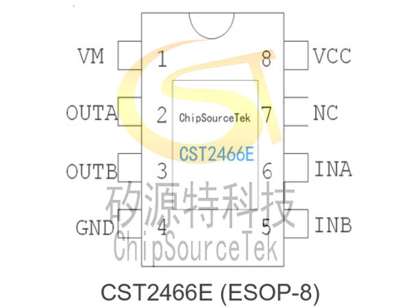
CST2466/CST2466E provides SOP8 and ESOP-8 packaging forms.
The CST2466/CST2466E circuit has a wide operating voltage range (from 2V to 11V), with a maximum continuous output current of 2.1A (ESOP) and a maximum peak output current of 3.5A.
CST2466/CST2466E provides SOP8 and ESOP-8 packaging forms.
CST2466/CT2466E Overview:
CST2466/CST2466E provides an integrated brushed DC motor drive solution for battery powered toys, low voltage or battery powered motion control applications.
The CST2466/CST2466E circuit integrates an H-bridge driver circuit designed with N-channel and P-channel power MOSFETs, which is suitable for driving a winding of a brushed DC motor or a stepper motor.
The CST2466/CST2466E circuit has a wide operating voltage range (from 2V to 11V), with a maximum continuous output current of 2.1A (ESOP) and a maximum peak output current of 3.5A. The driver circuit is equipped with an overheat protection circuit. When the load current through the driving circuit is much greater than the maximum continuous current of the circuit, due to the limitation of the packaging heat dissipation capacity, the junction temperature of the internal chip of the circuit will rapidly rise. Once it exceeds the set value (typical value of 150 ℃), the internal circuit will immediately turn off the output power transistor, cut off the load current, and avoid safety hazards such as smoke and fire caused by the continuous temperature rise of the plastic packaging. The built-in temperature hysteresis circuit ensures that the circuit is restored to a safe temperature before allowing for re control of the circuit.
CST2466/CST2466E provides SOP8 and ESOP-8 packaging forms.
The CST2466/CST2466E provides an integrated motor driver for cameras, consumer products, toys and other application with low-voltage or battery-powered motion control.
The CST2466/CST2466E can supply up to 2.1A of output DC current. It operates on a motor power supply (VM) from 2 to 11V and a device power supply voltage (VCC) of 2V to 6V. Ultra- low RDS-ON allows SOP-8 package available.
The CST2466/CST2466E has a PWM (INA、INB) input interface. Full protections are integrated with over-current protection, under-voltage lockout and over-temperature shutdown.
CST2466/CT2466E Feature:
CST2466/CT2466E ABSOLUTE MAXIMUM RATINGS
CST2466/CT2466E RECOMMENDED OPERATING CONDITIONS(Ta=25℃)
Note:The maximum continuous output current depends on the heat dissipation conditions. 2.1A(ESOP8) 1.68A(SOP8)
CST2466/CT2466E ELECTRICAL CHARACTERISTICS
(Ta=25℃,VCC=3V,VM=6V,unless otherwise specified )
CST2466/CT2466E INPUT AND OUTPUT TRUTH TABLE
CST2466/CST2466E provides an integrated brushed DC motor drive solution for battery powered toys, low voltage or battery powered motion control applications.
The CST2466/CST2466E circuit integrates an H-bridge driver circuit designed with N-channel and P-channel power MOSFETs, which is suitable for driving a winding of a brushed DC motor or a stepper motor.
The CST2466/CST2466E circuit has a wide operating voltage range (from 2V to 11V), with a maximum continuous output current of 2.1A (ESOP) and a maximum peak output current of 3.5A. The driver circuit is equipped with an overheat protection circuit. When the load current through the driving circuit is much greater than the maximum continuous current of the circuit, due to the limitation of the packaging heat dissipation capacity, the junction temperature of the internal chip of the circuit will rapidly rise. Once it exceeds the set value (typical value of 150 ℃), the internal circuit will immediately turn off the output power transistor, cut off the load current, and avoid safety hazards such as smoke and fire caused by the continuous temperature rise of the plastic packaging. The built-in temperature hysteresis circuit ensures that the circuit is restored to a safe temperature before allowing for re control of the circuit.
CST2466/CST2466E provides SOP8 and ESOP-8 packaging forms.
The CST2466/CST2466E provides an integrated motor driver for cameras, consumer products, toys and other application with low-voltage or battery-powered motion control.
The CST2466/CST2466E can supply up to 2.1A of output DC current. It operates on a motor power supply (VM) from 2 to 11V and a device power supply voltage (VCC) of 2V to 6V. Ultra- low RDS-ON allows SOP-8 package available.
The CST2466/CST2466E has a PWM (INA、INB) input interface. Full protections are integrated with over-current protection, under-voltage lockout and over-temperature shutdown.
CST2466/CT2466E Feature:
Single channel built-in power MOS full bridge driver
The maximum continuous output current can reach 2.1A, with a peak value of 3.5A
Drive forward, backward, stop and brake functions
No need for peripheral filtering capacitors
Built in hysteresis heating effect overheat protection function
Low on resistance 260m Ω
CST2466/CST2466E provides SOP8 and ESOP-8 packaging forms
H-Bridge Motor Driver
DC Motor or Other Loads
Low On-Resistance :280mΩ
2.1-A Maximum DC Drive Current
Separate Motor and Logic Supply
Motor VM : 2 to 11V
Logic VCC : 2V to 6V
Low-Stand-by Current ≤ 2uA/VM=VCC=5V
Small Package and Footprint
8-Pin ESOP with Thermal PAD
8-Pin SOPProtection Features
VCC Under-voltage Lockout
Over-Current Protection
Thermal Shutdown
CST2466/CT2466E APPLICATION:
Electric toothbrush
Toy motor drive
Camera, DSLR camera lens driver
Electronic lock
robot
Brushed driver application
Toy motor drive
Camera, DSLR camera lens driver
Electronic lock
robot
Brushed driver application
Electric toothbrush, Electric lock
Cameras
DSLR Lenses
Consumer Products
Toys
Robotics
CST2466/CT2466E PCB layout guidance and typical application circuit diagram:
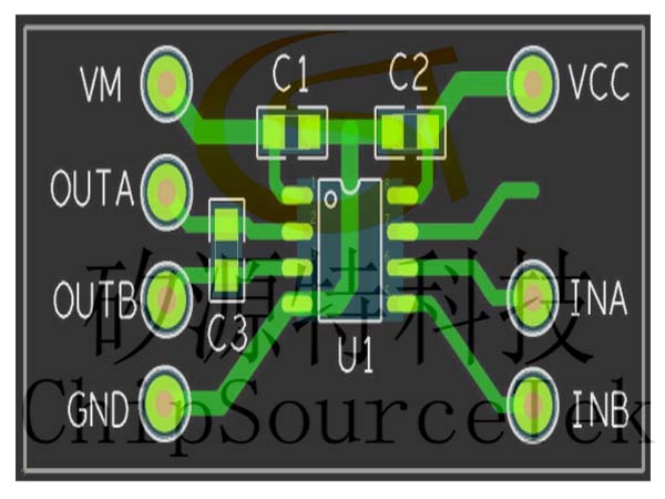
CST2466/CT2466E PCB LAYOUT GUIDANCE
Cameras
DSLR Lenses
Consumer Products
Toys
Robotics
CST2466/CT2466E PCB layout guidance and typical application circuit diagram:
CST2466/CT2466E PCB LAYOUT GUIDANCE
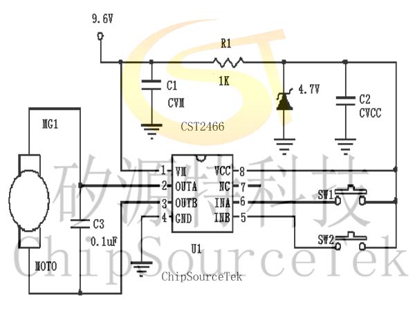
Note: In 3V applications, it is recommended to use at least one 0.1uF CVM capacitor as shown in the figure; Use at least one 1uF in 4.5V applications; Use at least one 4.7uF in 6V applications; Use at least one 22uF in 9V applications. All use surface mount capacitors placed near the VDD pin of the IC, and the connection between the negative terminal of the capacitor and the GND terminal of the IC should also be as short as possible. Even though the capacitors are close, the wiring and routing are far apart. When using a large electrolytic plug-in capacitor, it is recommended to connect another 0.1uF surface mount capacitor to the VM pin of CST2466/CST2466E. Refer to the following diagram.
The capacitor C1 connected between the GND and the VM pins must be located as close as possible to the CST2466/CST2466E chip. In different applications, C1(show as above) is recommended to use a 0.1uF in 3V applications; a 1uF is recommended for 4.5V applications; a 4.7uF is recommended for 6V applications; in 9.6V applications, it is recommended to use 22uF, all these capacitors should be SMD package. The connection between the negative pole of the capacitor and the GND terminal of the IC should be as short as possible. That is to say, the line route should not far away.
When the application board has capacitors while filtering for other chips that is far away from the CST2466/CST2466E, it need to place a small capacitor for CST2466/CST2466E.
The capacitor C3 preferably soldering to the motor poles instead of placing it on the PCB. When it is inconvenient to soldering on the motor poles, it can be mount on the PCB. The following diagram is the PCB layout reference .
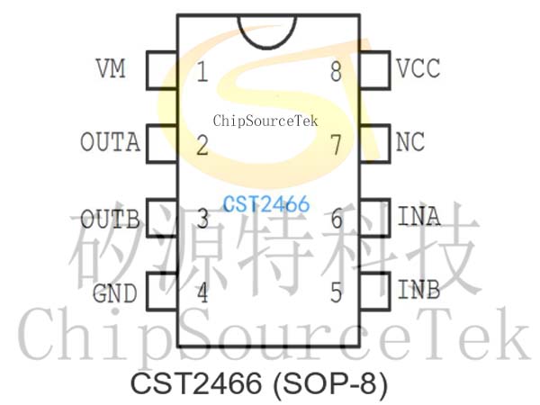
CST2466/CT2466E SOP8 PIN DESCRIPTION:
The capacitor C1 connected between the GND and the VM pins must be located as close as possible to the CST2466/CST2466E chip. In different applications, C1(show as above) is recommended to use a 0.1uF in 3V applications; a 1uF is recommended for 4.5V applications; a 4.7uF is recommended for 6V applications; in 9.6V applications, it is recommended to use 22uF, all these capacitors should be SMD package. The connection between the negative pole of the capacitor and the GND terminal of the IC should be as short as possible. That is to say, the line route should not far away.
When the application board has capacitors while filtering for other chips that is far away from the CST2466/CST2466E, it need to place a small capacitor for CST2466/CST2466E.
The capacitor C3 preferably soldering to the motor poles instead of placing it on the PCB. When it is inconvenient to soldering on the motor poles, it can be mount on the PCB. The following diagram is the PCB layout reference .
CST2466/CT2466E SOP8 PIN DESCRIPTION:
| Pin number | Pin name | I/O | Description |
| 1 | VM | -- | Motor power supply |
| 2 | OUTA | O | Motor drive output A |
| 3 | OUTB | O | Motor drive output B |
| 4 | GND | -- | Ground |
| 5 | INB | I | Logic input B |
| 6 | INA | I | Logic input A |
| 7 | NC | -- | No connection |
| 8 | VCC | -- | Logic power supply |
CST2466/CT2466E ABSOLUTE MAXIMUM RATINGS
| Parameters | Symbol | Value | Unit | |
| Logic power supply voltage , VCC | VCC | 7 | V | |
| Motor power supply voltage , VM | VM | 11 | V | |
| Power dissipation | Pd | SOP-8 | 0.96 | W |
| Operating Temperature, Top | Topr | -20~85 | ℃ | |
| Junction temperature | Tj | 150 | ℃ | |
| Storage Temperature, Tstg | Tstg | -55~150 | ℃ | |
| Manual welding temperature | 350~370 | ℃ | ||
| Peak output current | Iop | 3.5 | A | |
| Continuous Output Current | Ioc | 2.1 | A | |
| PWM Frequency | fPWM | 33 | KHz | |
CST2466/CT2466E RECOMMENDED OPERATING CONDITIONS(Ta=25℃)
| Parameter | Symbol | Rating | Unit |
| Power supply voltage | VCC | 2.0~6 | V |
| Motor Power supply voltage | VM | 9.6 | V |
| High Input Voltage | VIN | 0.5xVCC | V |
| Low Input Voltage | VIN | -0.8~0 | V |
| Continuous Output Current | IOUT | -1500~1500 | mA |
CST2466/CT2466E ELECTRICAL CHARACTERISTICS
(Ta=25℃,VCC=3V,VM=6V,unless otherwise specified )
| Parameter | Symbol | Test Condition | Min | Typ | Max | Unit |
| Overall Circuit | ||||||
| Standby Current | ICCST | INA=INB=GND | — | 1 | 5 | uA |
| Input control | ||||||
| High Input Voltage | VINH | 2 | 4 | 6 | V | |
| Low Input Voltage | VINL | — | — | 0.8 | V | |
| PWM Drive Frequency | FPWM | — | 20 | 33 | KHz | |
| Reverse brake Time Required | RVBT | from INA to INB or from INB to INA | 200 | 500 | — | uS |
| High Input Current | IINH | VIN=3V | — | 250 | 400 | uA |
| Low Input Current | IINL | VIN=0V | -1 | 0 | — | uA |
| Pull Down Resistor | RIN | — | 12 | — | KΩ | |
| Driving | ||||||
| Output Impedance(HS+LS) | RON | Io=±200mA | — | 0.26 | 0.6 | Ω |
| Protection Circuits | ||||||
| Thermal shutdown temperature | TTSD | Die temperature | — | 150 | — | ℃ |
CST2466/CT2466E INPUT AND OUTPUT TRUTH TABLE
| Input | Output | Function | ||
| INA | INB | OUTA | OUTB | |
| L | L | Hi-Z | Hi-Z | Stand-by(Stop) |
| H | L | H | L | A CH output |
| L | H | L | H | B CH output |
| H | H | L | L | Brake |

Please submit your basic information, send an email to Sales@ChipSourceTek.com, or call us at 13823761625 (same number as WeChat), and we will contact you as soon as possible!

WeChat Official Account

WeChat Service
 Email
Email QQ
QQ 13823761625
