
How to achieve a cost-effective 2x10W dual-channel boost solution with two CST8337s

2022/2/11
V1.0
Abstract
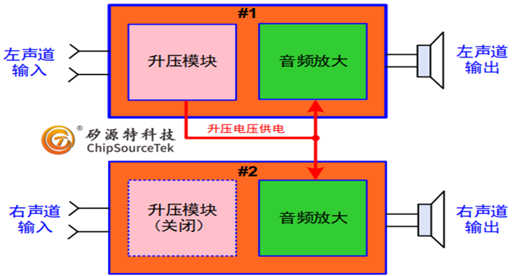
The CST8337, through the combination of two small-sized, high-power single-channel CST8337s with built-in boost, uses the boost of one to directly power the other. While saving a set of peripheral boost supporting circuits, it can achieve a dual-channel built-in boost of 2X10W power, thereby providing a cost-effective stereo solution.
Advantages of the plan
The CST8337 adopts the ESSOP-10 small volume package, and two CST8337s occupy a relatively small PCB area.
wo CST8337s only require one set of peripheral boost devices, inductors and Schottky diodes, optimizing the peripheral components of the overall solution.
The CST8337 features an AB/D class switchable function, which can address the issue in the market that high-power (2X10W) dual-channel built-in boost systems lack AB class boosting.
The CST8337 has a strong boost current capacity, providing an instantaneous input current of 8A, which can meet the power requirements of dual-channel systems.
The left and right channels are separated from each other, which offers better performance in suppressing crosstalk in stereo channels. The excellent power distortion can better meet customers' requirements for stereo sound quality.
Application circuit
To better illustrate this application scheme, Fig.2 illustrates the combined implementation circuits of CST8337 #1 and #2 as follows:
1、The VCTRL (Pin3) of #1 and #2 need to be connected together as the enable control pins of the entire system (which can control the switching between AB and D, but it should be noted that the enable should be turned off for at least 100mS when switching modes). The function is shown in the figure.
2、#1 has a complete peripheral circuit (including boost accessory devices), and the HPVDD after boost is directly connected to the HPVDD (Pin9) of #2.
3、Pins 6, 7 and 8 of #2 are suspended and no external components are required
4、The current capacity can be set through the Rlim resistor at the ILIMIT pin #1. It is generally not recommended to exceed 43k
5、It is recommended that the capacitor connected to ILIMIT be no less than 1uF. It should be noted that a capacitor value that is too small will cause a large starting current, which may damage the system.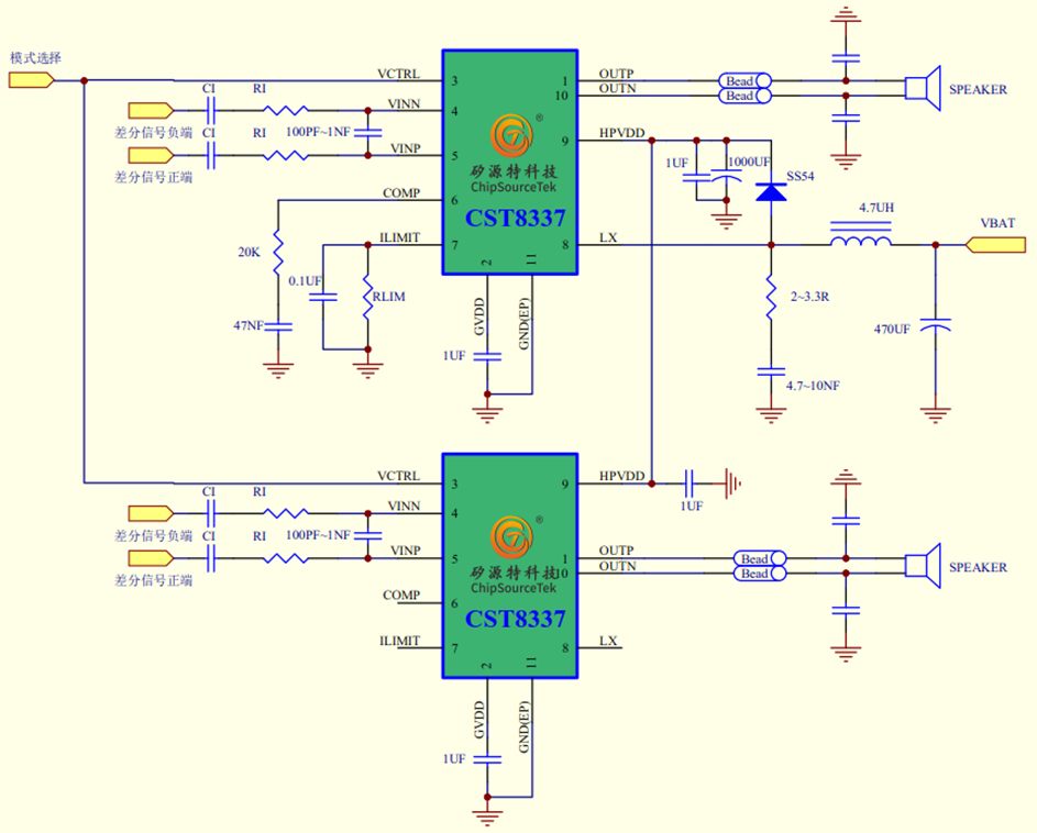
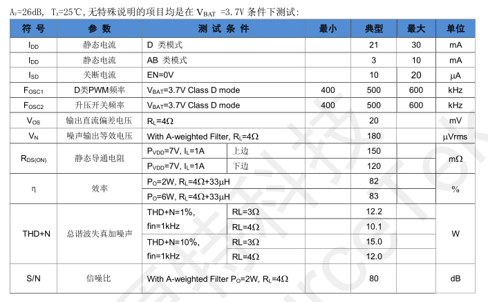
Electrical characteristics of CST8337
AV=26dB, TA=25℃,All items without special instructions were tested under the condition of VBAT =3.7V
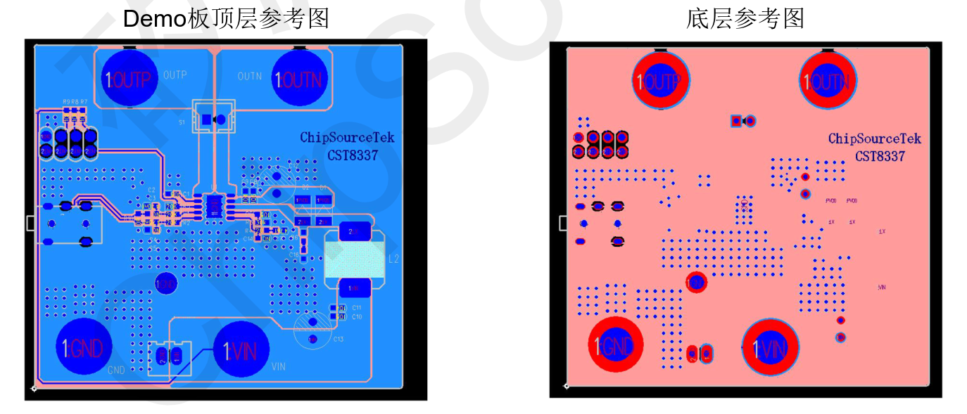
PCB Guide

WeChat Official Account

WeChat Service
 Email
Email QQ
QQ 13823761625
