The simple answer is that a low-pass filter (lpf) allows low frequencies to pass while blocking high frequencies. The classic example is the bass in an audio system. The low-pass filter allows the bass to be passed to the big bass, while the high-pass filter (hpf) allows the high frequency to be passed to the high pitch. There may even be a bandpass filter that allows the mezzo (speech) signal to be passed to the mezzo speaker.
In this example, the filter is used to mitigate the physical effects associated with the speaker. The bass is delivered to a large transducer that is able to move large amounts of air to provide thunderous bass, while the treble is better produced by a smaller device.
To fully understand the meaning and operation of filters, we need a working mental model to distinguish between the time domain and the frequency domain. We must master the language used to describe the variable frequency signal so that we can design and subsequently evaluate the performance of the filter.
This article will point out these foundations. It gives the simulation results of an ideal first-order low-pass RC filter, and then summarizes the dangers that students may encounter. Specifically, it is the problem encountered when the filter is used in a non-ideal environment of a non-ideal element.
What is the basis for the existence of filters?
Traditional electronics courses introduce filters between discrete transistor amplifiers and operational amplifiers. Unfortunately, we don't have more time to explore the rich language associated with frequency domain analysis. In fact, many students will try to describe filters without having used a spectrum analyzer before. In a related and perhaps equally frustrating case, you might take a digital logic course to explore how low-pass (anti-aliasing filters) can be applied to ADCs. Things may get better when you finally finish the Signals and Systems course. Until then, keep reading this article.
Technical Tips:
Low-pass filters are usually used before analog-to-digital converters (ADCs). The low-pass filter is used as an anti-aliasing filter to prevent objectionable distortion forms. The reason for this distortion is related to the Nyquist sampling theorem, which tells us that the highest ADC input frequency must be less than half the sampling frequency. For example, a system designed for speech frequencies can have a sample rate of 6 KHZ. Any tone above 3 KHZ will cause signal distortion.
No doubt this is a complex Goldi knot and is most likely the reason you are visiting this page. Filters are a challenging concept because their application requires many related but fundamental concepts such as frequency domain analysis, bandwidth, resonance, harmonics, Fourier series, and decibels. Each one is complicated, but may make you feel like you're drinking from a fire hose.
A complete solution is beyond the scope of this article. Instead. Allow me to introduce you to some useful videos. Video 1 demonstrates the spectrum encountered in the kitchen. It's a near-perfect sonic introduction that sets the stage for the way to think about filters. The second video is part of my Communication Systems lecture series. It offers multiple ways of thinking about the spectrum. It builds on the previous circuit I and Circuit II phasor calculations and uses radio broadcasting to explore bandwidth. Finally, it presents a simulation involving low-pass filters, high-pass filters, band-pass filters and notch filters.
Calculation of ideal low-pass filter
The textbook definition of a low-pass filter is as follows:

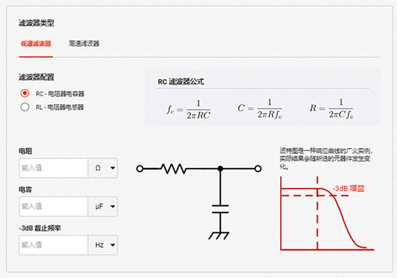
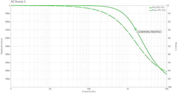
Let R = 1.0kΩ, C = 0.1uF. The result is a -3dB cutoff of about 1.6 kHz. Online DigiKey low-pass filter calculator, as shown in Figure 1. The results of the Multisim frequency scan are further supported in Figure 2, which is presented using a linear scale. In this graph, you can see that the amplitude drops from 1.0V for the input to 0.71V for the output.

图 1 :R = 1 kΩ和C = 1 uF的DigiKey RC低通滤波器计算器的图像。得到的截止频率约为1.6 kHz。

Technical Tips:
The term "cutoff" is often misunderstood. In the context of a low-pass filter, the cut-off frequency means that the output signal is 70.7% of the input signal. This can be expressed in decibels as -3 dB. It is important to realize that the signal decreases significantly at the cut-off point. The actual attenuation gradually starts at lower frequencies.
Problems that arise when we deviate from the ideal low-pass filter
In the previous section, we were careful to use the word "ideal" when describing the filter. The term applies both to the filter itself and to the way the filter is used. As for filters, the term "ideal" means that the component operates in an ideal way (see technical tips). As for the output, we assume that the filter is disconnected from any load. In other words, we assume that the output of the filter is looking for an infinite impedance.
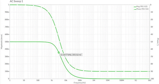
A typical mistake is to input the output of the filter into the inverted op-amp. Assume that this amplifier has a gain of 10 and uses 1.0 kΩ and 10 kΩ resistance pairs. Taking into account the virtual ground of the op amp, the filter will see a 1 kΩ load. For low frequencies, the filter output amplitude is no longer uniform. In fact, for our chosen resistor, we have formed a voltage divider that halves the output at low frequencies. Our cutoff frequency has also shifted. Without explanation, we should relearn Thevenin's theorem and start with AC analysis.

Figure 3: Results of the MultiSim frequency scan show significant deviations when the filter is loaded with a 1kΩ load. This change in frequency has serious implications. For example, someone who does not understand this ideal distinction can design a crossover for a woofer in a speaker system. We can see that they will be seriously disappointed with the results, as the frequency and attenuation levels are far from ideal. To make matters worse, the speakers themselves didn't perform particularly well. For example, it has a physical resonance that varies according to the damping of the enclosure. This creates a reactive component that changes the load on the filter.
conclusion
It's a fascinating point of study where theory meets the real world. A low-pass filter is anything but simple. Keep these ideas in mind when designing your circuit. Maybe that's why many people call it art.
免责声明: 本文章转自其它平台,并不代表本站观点及立场。若有侵权或异议,请联系我们删除。谢谢! Disclaimer: This article is reproduced from other platforms and does not represent the views or positions of this website. If there is any infringement or objection, please contact us to delete it. thank you! |


