
Lead-acid batteries, like lithium batteries, should not be overcharged or overput. However, when the lithium battery is used, it is generally combined with the protection board to achieve overcharge and discharge, short circuit and other protection. However, lead-acid batteries are generally used independently, and overcharge and discharge require human control or protection by the charge and discharge circuit inside the load. When charging the battery, the finished charger or charge management chip is generally used, and the voltage sampling inside the charger and the charge management chip generally design the overcharge protection circuit and the secondary charge protection circuit. Therefore, during the use of the battery, it is often easy to overdischarge. Let's pass a simple circuit to achieve the protection function of the battery overdischarge.
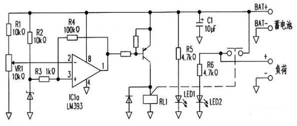
The circuit structure is relatively simple, using a common chip voltage comparator chip -LM393. This is a dual voltage comparator chip, one of which is used in this circuit. The working principle of this circuit is that in addition to supplying power to the load part, the battery will also provide power to this circuit. The in-phase input terminal of the voltage comparator is regulated by resistor R2 through the regulator diode, and the reference voltage is provided by resistor R3. At the same time, the battery voltage is entered into the reverse phase input terminal of the voltage comparator through the partial voltage input of resistor R1 and variable resistor VR1, which is used as the detection of the battery voltage, and the voltage is adjusted to the discharge protection voltage by adjusting VR1. In normal operation, the voltage of the inverting input will be higher than that of the in-phase input, and the output of the comparator will output a low level to drive the external PNP triode on, the relay coil will be powered to work, the normally open contact will be closed, and the battery will supply power to the load.
When the battery voltage is too low, the inverting input voltage will be lower than the in-phase input, the state of the comparator will be flipped, the output from low level to high level, the transistor is cut off, the relay coil loses voltage, and the contact is disconnected to stop the power supply. This is how this circuit works and is the basic application of voltage comparators. However, when the battery voltage decreases with the discharge, there will be a moment when the voltage of the in-phase input is equal to that of the inverting input. At this time, the judgment of the voltage comparator is at a critical value, and the output state will become unstable, which is manifested as the relay contact constantly on and off. In addition, when the battery is disconnected from the load, the voltage will also rise, which will also cause instability in the output state of the comparator. To avoid this problem, add the electric R4.
When the battery voltage is too low to make the comparator output high voltage, the output voltage will be returned to the in-phase input through the resistor R4, at this time the voltage at the in-phase input will increase, if the battery voltage rises, if you want the comparator output state to flip, it needs to be higher than the voltage value of the undervoltage protection. This makes the voltage difference between the undervoltage detection voltage and the recovery voltage, and this voltage is the back-difference voltage, or called hysteresis. In this way, the problem caused by the voltage critical value is effectively avoided.
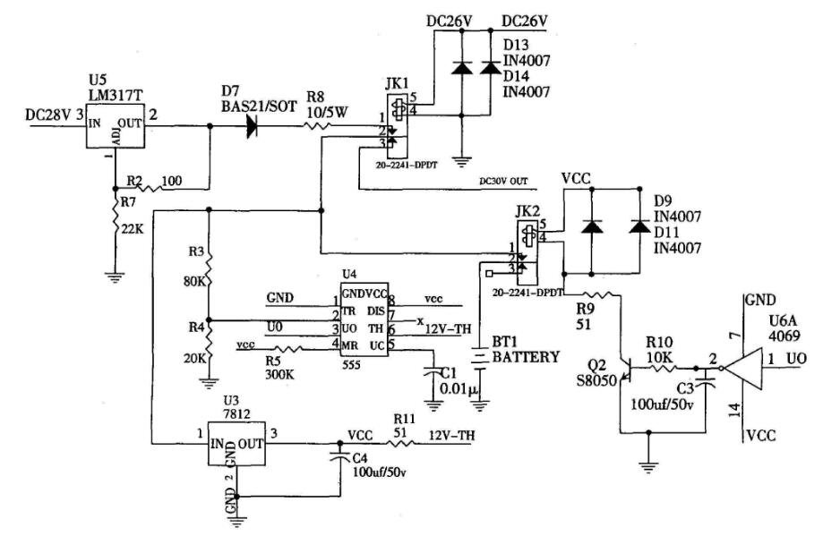
Lead-acid battery charging and discharging protection circuit diagram (2)
免责声明: 本文章转自其它平台,并不代表本站观点及立场。若有侵权或异议,请联系我们删除。谢谢! Disclaimer: This article is reproduced from other platforms and does not represent the views or positions of this website. If there is any infringement or objection, please contact us to delete it. thank you! |

WeChat Official Account

WeChat Service
 Email
Email QQ
QQ 13823761625
