
As the designers of these systems have made great strides in improving the robustness of their systems and improving audio quality, modern Class D solutions are already a great improvement over previous generations. In fact, in most applications, the advantages of using these amplifiers now outweigh any disadvantages associated with them.
In traditional Class D amplifiers, the controller is typically used to convert analog or digital audio into a PWM signal, which is then amplified by a power MOSFET, which is typically integrated into a power back-end device. These amplifiers have the advantage of high efficiency, reduced or reduced heat sinks, and reduced power supply output requirements. However, they also have inherent system issues, such as cost, performance, and EMI, compared to traditional Class A/B amplifiers. A new trend in Class D amplifiers aims to solve these problems.
Reduce EMI
One problem that has plagued system designers since the introduction of Class D is the large amount of radiated EMI due to the rail-to-rail switching characteristics of the amplifier. This will cause the device to fail the required FCC and CISPR certifications.
In a Class D modulator, digital audio can be converted to PWM by comparing the audio waveform with a high-frequency constant waveform and modulating the result to a fixed carrier frequency. The resulting signal is a fixed carrier frequency of a variable pulse width (typically hundreds of kilohertz). A higher voltage power MOSFETs are then used to amplify this PWM signal. The amplified PWM signal passes through a low-pass filter, which eliminates the carrier frequency and restores the original baseband audio signal.
While this topology works, it leads to some unnecessary artifacts, such as large amounts of radiated EMI. Since the modulator uses a fixed carrier frequency, the harmonics of that carrier will radiate out. Similarly, due to the switching nature of the PWM signal, overshoot/undershoot and ringing produce a fixed rate of high frequency (10 to 100 MHz region) radiated EMI component. In order to resist radiated EMI, the main trend of the latest generation of PWM modulators is to adopt spread spectrum modulation.
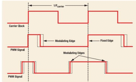
In conventional PWM, EMI is corrected by changing the two edges of the signal.
Spread spectrum modulation is used in a variety of applications to extend the spectral energy of a switching PWM signal to a larger bandwidth without changing the original audio content. An effective way to correct a high-EMI conventional PWM modulator is to change the two edges of the switching PWM signal, as shown in Figure 1.
The signal is centered on the carrier frequency, but neither edge is a repeating cycle. This has the benefit of maintaining a constant carrier frequency, but because the edges are not switched at a constant rate, the radiated energy at the carrier frequency (and associated harmonics) is greatly reduced.
免责声明: 本文章转自其它平台,并不代表本站观点及立场。若有侵权或异议,请联系我们删除。谢谢! Disclaimer: This article is reproduced from other platforms and does not represent the views or positions of this website. If there is any infringement or objection, please contact us to delete it. thank you! |

WeChat Official Account

WeChat Service
 Email
Email QQ
QQ 13823761625
