
How the new device achieves a higher energy efficiency ratio and better thermal performance than the previous generation of high-current step-boost µModule regulators.
By Ling Jiang, Wesley Ballar, Anjan Panigrahy and Henry Zhang, Analog Devices
Many applications require a wide range of input and/or output voltages, such as battery-powered systems. In situations where the input voltage may be lower or higher than the output voltage, the power supply needs to adjust its output voltage. As long as grounding isolation is not required, the four-switch buck-boost topology provides ultra-high efficiency and power density for such applications. In addition, buck-boost regulators are very flexible and can be used as a pure buck power supply or a boost (with short circuit protection) power supply.
Analog Devices' µModule division develops a wide range of step-down and boost regulators. The LTM8045, LTM8049, LTM8083 and LTM4693 are suitable for low current applications. The LTM4607 series, the LTM8055 series, and the newly released LTM4712 buck-boost modules support high current applications (up to 12 A). The LTM4607/LTM4605/LTM4609 series has integrated controllers and MOSFETs internally, but requires external power inductors and detection resistors (RSENSE) to be connected on the PCB to form a complete power solution, as shown in Figure 1. The LTM8054, LTM8055, and LTM8056 integrate power inductors and RSENSE into the µModule package, simplifying customers' design and layout efforts, as shown in Figure 2. Compared to the LTM4607 series, the LTM8055 series offers a smaller size solution, but its output current is limited by small size integrated inductors, which has certain limitations in terms of thermal performance and efficiency.
In 2023, ADI released its new high-current, four-switch step-up-voltage regulator, the LTM4712. It is A 36 VIN (Max), 12 A power module in a high-density 16 mm x 16 mm x 8.34 mm BGA package. It uses ADI's proprietary advanced component packaging technology to integrate high-performance power inductors into the package. Figure 3 shows the proprietary current detection scheme integrated in the module. This not only saves space, but also effectively reduces additional power loss. The device features an advanced buck-boost controller and advanced ADI package that enables ultra-high power levels, power density, efficiency and excellent thermal performance over a wide input and output voltage range.
The LTM4712 features fast cycle by cycle current mode control for reliable protection and smooth mode transition. It contributes to excellent current sharing when a parallel configuration is used to support higher current applications. In addition, the new device supports an optional constant output current mode that can be used for battery charging applications, while also allowing for redundant inputs, enhancing its versatility as a redundant power source.
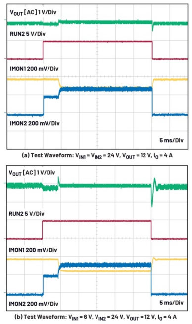
Figure 1: Schematic diagram of the LTM4607 power stage
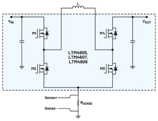
Figure 2: LTM8055 typical application circuit
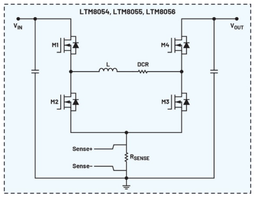
Figure 3.LTM4712 Typical application circuit
Increased efficiency and improved thermal performance
Figure 4 compares the efficiency of the LTM4607, LTM8055, and LTM4712 at 6 V VIN, 12 V VIN, 24 V VIN, and 12 V VOUT. The evaluation used standard evaluation boards that can be ordered online. According to the test results, the LTM4712 is significantly superior to the other two products in terms of efficiency and current capability.
At 12 V VIN and 12 V VOUT, the LTM4712 is 30°C cooler than the LTM8055 while doubling power. For applications that require 12 A currents, if the LTM8055 is used, two or three of these devices may need to be connected in parallel, depending on the cooling system. However, if the LTM4712 is used, then one device is sufficient, the PCB space is greatly reduced, and the circuit design is simpler.
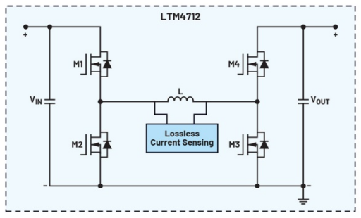
Figure 4: Efficiency comparison between LTM4712, LTM4607, and LTM8055
Good current sharing in parallel configuration
The LTM4712 supports parallel configuration, allowing for higher output power with simple setup. Thanks to current mode control, it has excellent current sharing performance. The EVAL-LTM4712-A2Z evaluation kit demonstrates four modules operating in parallel, providing A total output current of 48 A.
When the device is used to realize parallel configuration, the design and configuration of the evaluation board must be consulted. In order to achieve effective current sharing, COMP pins and FB pins need to be connected when parallel modules are connected. The PHMODE pin can be used to configure the phase shift. In the case of four modules in parallel, the PHMODE pin connected to the INTVCC produces a 90° phase shift for excellent interleaving. In addition, to achieve frequency synchronization, the CLOCKOUT signal of the first module shoul
Optional constant current regulation
The LTM4712 can be used as a constant output current source, making it suitable for applications such as battery chargers or LED drivers. The load current is set by an external output current detection resistor near the ISET pin and output. The formula VSENSE = IOUT × RSENSE_IOUT defines the voltage representing the average output current. The maximum VSENSE is determined by the voltage on the ISET pin and ranges from 0.2V to 1.2V, corresponding linearly to 0 mV to 50 mV. The ISET pin voltage VISET is determined by an internal current source of 15 μA and a resistance RISET connected between the ISET pin and the ground, expressed as VISET = 15 μA × RISET. Therefore, the output current is calculated as: IOUT = (VISET-0.2V)/(20 × RSENSE_IOUT).
It should be noted that when the ISET pin floats, or when the ISET pin voltage exceeds 1.2V, the internal circuit limits the maximum VSENSE to 50 mV. Due to the presence of ripple current in the output, RC filters must be used on the ISP and ISN pins to achieve accurate average current detection. In addition, when selecting the feedback resistance between the FB pin and the ground, ensure that it produces an output voltage higher than the target VOUT.
Redundant power supply
4712 supports applications that require redundant input. It can be used in systems that require backup power, or those that draw power from different input sources to support common loads. Figure 5 shows an example circuit where two modules are powered by different inputs (VIN1 and VIN2) that together provide A 12 V output for a 24 A load. It is important to note that any input voltage drop does not affect output regulation, and by connecting the COMP pins, peak inductance current sharing is always effective.
Figure 6 shows the table test waveforms under two different conditions. Figure 6a shows how both phase 1 and phase 2 operate in step-boost mode. Initially, phase 1 provides 4 A load current, and after phase 2 is activated, the two gradually share half of the load current. The IMON waveform shows that when both phases are in operation, the two phases equally share the load current.
Figure 6b shows the same load conditions with different inputs. Here, phase 1 runs in boost mode, while phase 2 runs in buck mode. Since the COMP pins are connected together, the peak inductance current of both phases is the same. Therefore, the output current of phase 1 (boost) is lower than the output current of phase 2 (buck). The specific load current provided by each phase can be calculated based on parameters such as inductance, switching frequency, VIN, VOUT, and total load current. In this example, phase 1 provides 1.4 A load current, while phase 2 provides 2.6 A load current.
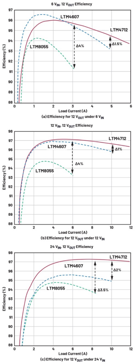
Figure 5: Input redundant application circuit
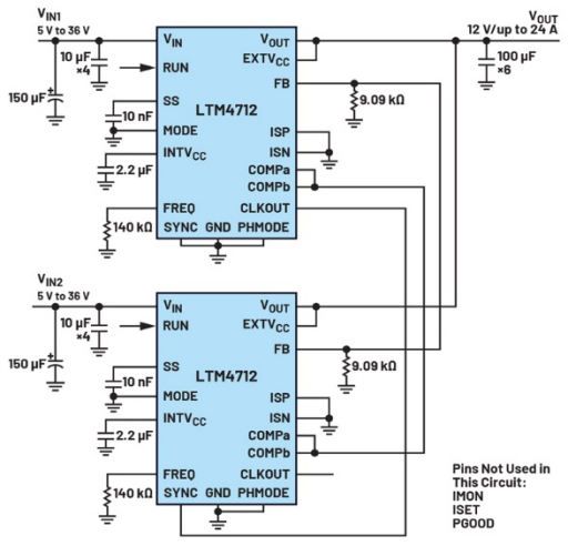
Figure 6: Input redundant application circuit
Conclusion
Not only can the LTM4712 be easily shunt in parallel to support higher power applications, but it also exhibits good current sharing capability in parallel configurations. The device can be flexibly configured for a constant current output, making it ideal for battery charging systems or LED applications. In addition, it supports redundant inputs, further improving its adaptability.
免责声明: 本文章转自其它平台,并不代表本站观点及立场。若有侵权或异议,请联系我们删除。谢谢! Disclaimer: This article is reproduced from other platforms and does not represent the views or positions of this website. If there is any infringement or objection, please contact us to delete it. thank you! |

WeChat Official Account

WeChat Service
 Email
Email QQ
QQ 13823761625
