1, stepless voltage regulation (flow) charger
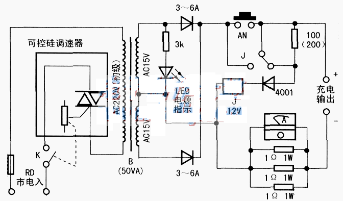
The purpose of stepless voltage regulation can be achieved by adjusting the input power frequency voltage by connecting a commercial fan governor (oven temperature regulator) in series at the primary of the rectifier transformer. Although the output waveform is not good, the practice proves that it is feasible.
When charging, as long as the charging current is adjusted to meet the requirements, the voltage is certainly appropriate. (Except that the battery itself is faulty).
Only when the battery polarity is connected correctly, the relay will pull on the charging circuit.
When the battery remains too little, or charge the battery below 12V, the charger needs to be connected to the mains, press AN to help start. The 100Ω resistance maintains the J suction. The contact capacity of the relay should be greater than. 10A(double contacts in parallel).
The negative loop has three 1-ω resistors (=0.333Ω), which are used to form a differential pressure detection current. The higher the output voltage and the greater the current, the greater the voltage drop. Ammeter is actually a voltmeter, but the setting value is the current number. I use a cheap 91L16300V small square meter, remove the 220k step-down resistor connected in the table, and re-adjust the standard value.
The following figure is the basic circuit of the stepless voltage regulator charger. When making it, the capacity and secondary voltage of the rectifier transformer and the rectifier diode can be selected according to the needs.
Charging current selection: 4 ~ 6Ah, select below 500mA; 7 ~ 15Ah. Select 800mA-1.5A; 15Ah is 2A above.

2, high frequency and efficient charger
High frequency charger, small body, light weight, fast charging, battery has no obvious memory effect.
Left of the dotted line below. It is a ready-made waste 60W energy-saving fluorescent lamp electronic ballast circuit, the printed board is small, and the whole piece is used. The output line connecting the two ends of the lamp tube is connected to the primary of the modified color TV switching transformer.
When the switching transformer is reformed, the primary and inter-stage insulation is completely retained (the primary inner layer and the winding do not care about it), remove all the secondary winding, and write down the number of turns in order to calculate the volt per turn, generally 0.46V ~ 0.60V per turn, and then use about 0-7mm enamelled wire to rewind the number of voltage turns you need. Take a few more heads in the middle, and by then, the estimation can not be used according to the situation. Selected winding voltages: half wave rectification, charging bottle voltage V(nominal)×2.5. For example: nominal 12V battery ×2.5, equal to 30V(AC). Full wave rectifier halved.
1HB is a small loop with positive and negative feedback. If it is difficult to start with light load (no output), its L1 can be increased by 1 to 2 turns.
When the charging flow exceeds 1A, V1 and V2 will be a little hot, remove the appropriate heat sink, stand in another position, and then connect the original circuit board with a wire.
Dashed right, rectifier and charging output circuit. ZK, easy to charge 6V, 12V battery conversion. ZK contact capacity should be greater than 5A, and try to do static operation (before power).
Rectifier tube D1, be sure to use high-frequency diode, ordinary power frequency diode or rectifier bridge, slow recovery speed, large loss, serious heat and damage (abandoned VCD, VCD power supply board).
R11. There will be a voltage drop when charging, and the higher the current, the higher the voltage drop. This pressure difference just points to an LED for charging indication, do not charge point is not bright. The charging output should be clearly connected to the electric column in red and black.
Charging current selection, refer to the previous description.
This charger has high frequency and high voltage, and should be installed in a box to ensure safety. The 2HB primary must not be allowed to open with the left circuit. Otherwise, the left circuit will have a thousand volts of upper high voltage (no-load), causing damage to the left circuit.
免责声明: 本文章转自其它平台,并不代表本站观点及立场。若有侵权或异议,请联系我们删除。谢谢! Disclaimer: This article is reproduced from other platforms and does not represent the views or positions of this website. If there is any infringement or objection, please contact us to delete it. thank you! |


