
1. introduction
As a backup power supply when the power system is outage, the battery has been widely used in industrial production, transportation, communication and other industries. If the battery fails or the capacity is insufficient, it may cause major accidents, so it is necessary to carry out comprehensive online monitoring of the battery's operating parameters. One of the important indicators of the state of the battery is its internal resistance. Whether the battery is about to fail, the capacity is insufficient, or the charge and discharge are improper, it can be reflected in its internal resistance changes. Therefore, the working state of the battery can be evaluated by measuring the internal resistance of the battery. At present, the common methods for measuring the internal resistance of batteries are:
(1.1) Density method
Density method is mainly used to measure the density of battery electrolyte to estimate the internal resistance of the battery. It is often used to measure the internal resistance of the open lead-acid battery, and is not suitable for the internal resistance measurement of the sealed lead-acid battery. The application range of this method is narrow.
(1.2) Open circuit voltage method
The open circuit voltage method is to estimate the internal resistance of the battery by measuring the terminal voltage of the battery, the accuracy is very poor, and even the wrong conclusion is reached. Because even if the capacity of a battery has become very small, its terminal voltage may still behave normally in the state of recharging.
(1.3) DC discharge method
The DC discharge method is to measure the instantaneous voltage drop on the battery through the instantaneous high current discharge, and calculate the internal resistance of the battery through Ohm's law. Although this method has been widely used in practice, it also has some shortcomings. If this method is used to detect the internal resistance of the battery, it must be carried out in the static or offline state, and can not be measured online. And the large current discharge will cause greater damage to the battery, thus affecting the capacity and life of the battery.
(1.4) AC injection method
By injecting a constant AC current signal IS into the battery, the voltage response signal Vo at both ends of the battery is measured, and the phase difference θ between the two is derived from the impedance formula

To determine the internal resistance R of the battery. This method does not need to discharge the battery, and can safely detect the internal resistance of the battery online, so it will not affect the performance of the battery. However, this method needs to measure the AC current signal Is, the voltage response signal Vo, and the phase difference θ between voltage and current. Therefore, this method not only has many interference factors, but also increases the complexity of the system, and also affects the measurement accuracy.
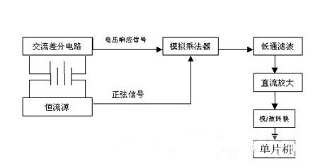
In order to solve the defects of the above methods, the four-terminal measurement method is adopted in this paper. The voltage response signal on both ends of the battery is multiplied by the AC differential circuit and the sine signal generating a constant AC source through the analog multiplier, and then the output voltage signal of the analog multiplier is passed through the filter circuit to convert the AC signal into the DC signal. After the DC signal is amplified by the DC amplifier, the ADC is converted, and the converted value is sent to the MCU for simple processing.
2. Principle of battery internal resistance detection
Because the internal resistance of the battery is milliohm level, the measurement error is large by using the conventional two-terminal measurement method, and the four-terminal measurement method is used here. When measuring, two terminals apply a constant AC excitation current signal with a frequency of 1.0kHZ±0.1kHZ, and the other two terminals are used for measurement. As shown in Figure 1, the response signal refers to the AC voltage signal measured at both ends of the battery after it is injected into the AC constant current source. The sinusoidal signal is the input signal generated by D/A as the voltage-controlled constant current source.
After passing the analog multiplier:
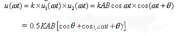
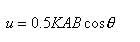
K is the amplification factor of the analog multiplier. After low-pass filtering, the AC component is filtered out to obtain:
From the principle of measuring internal resistance by AC method:

Where I is the maximum value of AC constant current source signal.
Comparison can be obtained:
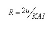
In the above formula, K, A and I are all known quantities, and u is the sampling value sent to the microcontroller for processing after A/D sampling, so a simple division operation in the microcontroller can obtain the internal resistance of the battery.
3. Design of AC constant current source
The prerequisite for the successful detection of battery status is the availability of the required AC constant current source. Constant current source is a power supply device that can provide a constant current to the load. It is a power supply with very large internal resistance. In order to ensure that the internal resistance has high measurement accuracy and better reproducibility, the constant current current source is required to have sufficient stability and the waveform distortion is small. The required AC signal amplitude is 40mV and the frequency is 1KHZ.
However, there are many shortcomings in the design of the traditional low-frequency AC signal generator: the application of general circuits, many components, especially the large volume of capacitors, and the stability of the waveform is poor, the distortion is large, and the adjustment is very inconvenient; Application-specific circuits, such as ICL8038, MAX038, etc., have significantly improved distortion and stability, but they are not suitable for low-frequency applications, inconvenient adjustment, and high cost.
3.1 Design Principles
This paper adopts digital signal generator to generate standard sine wave and current negative feedback method to generate accurate AC constant current source. The principle of AC constant current source is shown in Figure 2.
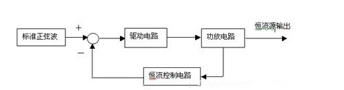
The circuit composition block diagram is shown in Figure 2: This is a closed-loop control system, current negative feedback circuit. The standard sine wave produces a 1KHz sine wave signal with stable frequency, symmetry, and low distortion. The drive circuit amplifies the sine wave to push the power amplifier circuit and get a sinusoidal AC current output. The signal obtained from the power amplifier output of the constant current control circuit is compared with the given signal to adjust the signal of the drive circuit, so that the output current remains stable.
3.2 Generation principle of standard sine wave
The standard sine wave signal is generated by a digital signal generator. First of all, the sinusoidal table data is stored in the sinusoidal signal memory, the crystal oscillator generates the oscillation frequency f, which becomes the complete square wave frequency through the integral circuit, and then the frequency is f/R through the frequency division circuit, and then through the phase discriminator FD and the loop filter LF circuit phase-locked frequency division, the sine value stored in the sinusoidal signal memory is read. After A D/A conversion circuit and a low-pass active filter filter circuit, the standard sine wave required in Figure 2 is generated.4. Sum up
Compared with the prior art, the treatment method has wide application range, high measurement accuracy, little damage to the battery, and can carry out safe online monitoring and management of the battery. At the same time, the internal resistance of the battery can be obtained without AC sampling and cos solution. This simplifies the complexity of the hardware and software required to measure the AC voltage and phase difference at both ends of the battery in the AC injection method. This method can meet the requirements of battery detection, and has obtained good practical results, and completed the performance detection and fault diagnosis of lead-acid battery. This paper provides a practical method for on-line detection of battery.
免责声明: 本文章转自其它平台,并不代表本站观点及立场。若有侵权或异议,请联系我们删除。谢谢! Disclaimer: This article is reproduced from other platforms and does not represent the views or positions of this website. If there is any infringement or objection, please contact us to delete it. thank you! |

WeChat Official Account

WeChat Service
 Email
Email QQ
QQ 13823761625
