
1 Basic concept of resistance-capacitance voltage reduction
1.1, what is resistance and capacitance pressure reduction?
Resistance-capacitance reduction is a circuit that uses the capacitive reactance generated by a capacitor at a certain frequency of AC signals to limit the maximum operating current.
The capacitor actually plays a role in limiting the current and dynamically distributing the voltage between the capacitor and the load.
1.2, which parts of the resistance-capacitance buck circuit is composed of?
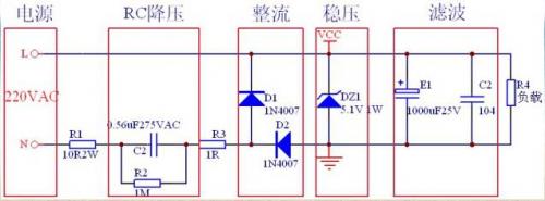
The resistance-capacitance buck circuit is composed of buck module, rectifier module, regulator module and filter module.
1.3 Basic design elements of resistance, capacitance and pressure reduction
When designing the circuit, we should first determine the maximum working current of the load, and calculate the capacitance value through this current value, so as to select the appropriate capacitance.
The difference between this and the linear transformer power supply: the resistance-capacitance step-down power supply is selected by the load current; A linear transformer power supply is a transformer selected by load voltage and power.
Resistance-capacitance buck current calculation
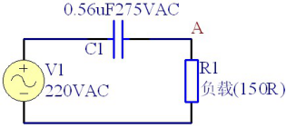
The resistance-capacitance buck circuit can be equivalent to the buck capacitor C1 and the load resistor R1, the resistor and the capacitor in series voltage division.
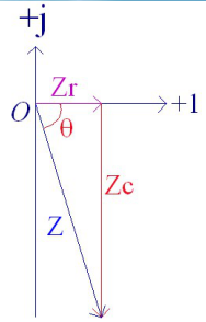
The capacitive reactance of C1 is Zc=-j/wC=-j/2πfC
The impedance of resistor R1 is Zr=R
The total equivalent impedance is Z=Zc+Zr=-j/2πfC+R
So I=U/Z=U/(Zc+Zr)=U/(-j/2πfC+R)
This leads to:
I=U/Z=U/Zc=U/(-j/2πfC)
=220*2π*f*C*j
=220*2π*50*C*j
=j69000C
I=|I|∠90°, effective current I1=|I|=69000C. When half wave rectifier is used, I1=0.5|I|=34500C.
Design example
Known conditions: load working current 15mA, working voltage 5V. Find the step-down capacitance value?
The half-wave rectification mode is adopted, and according to the calculation formula I1=0.5|I|=34500C, C=0.43uF. Therefore, a 0.47uF capacitor is selected here, which in turn can verify that the provided current I1=34500C=16.2mA, and excess current flows through the regulator.
Advantages of resistance-capacitance voltage reduction:
Small size; Low cost.
Disadvantages of resistance-capacitance step-down:
Non-isolated power supply, unsafe;
Cannot be used for high power load;
Incompatibilities and inductive loads;
Not suitable for dynamic loads.
2, the basic principle of resistance and capacitance reduction
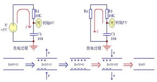
2.1 Principle of capacitor charging and discharging
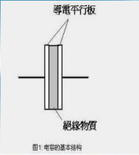
A capacitor is a passive device that stores energy in the form of an electric field. The essence of capacitor charge and discharge process is the process of two conductive parallel plates obtaining and releasing electrons.
Capacitor charging:
When the electric field strength E in the capacitor is less than the external power supply voltage U at both ends of the capacitor, the capacitor starts to charge. At this time, the positive electrode of the capacitor continues to lose electrons, the negative electrode continues to gain electrons, and the internal electric field E continues to increase until it is equal to the external voltage U, and the charging ends.
Capacitive discharge:
When the electric field strength E in the capacitor is greater than the external power supply voltage U at both ends of the capacitor, the capacitor starts to discharge. At this time, the positive electrode of the capacitor continues to gain electrons, the negative electrode continues to lose electrons, and the internal electric field E continues to weaken until it is equal to the external voltage U, and the discharge ends.
Dc charging and discharging process of capacitor
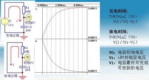
Since V0=0V, Vt=1V, V1=5V, R=10K, and C= 0.1uf, T= 10000*0.1*0.000001*Ln (5/4)=223uS
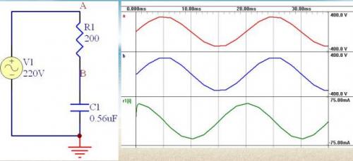
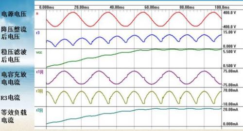
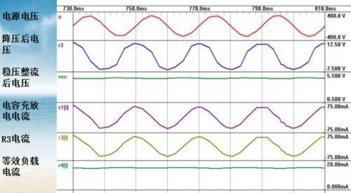
Ac charging and discharging process of capacitors
The DC charging and discharging of the capacitor is completed at one time, while the AC charging and discharging is a constantly repeating process.
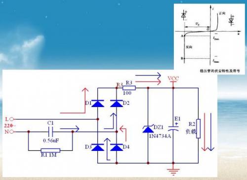
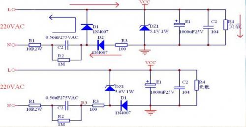
Full wave rectifier circuit
Half wave rectifier circuit
Function and selection of each component
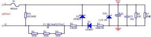
F1: Fuse, overcurrent protection, choose 400mA250V model.
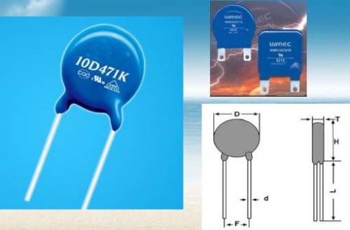
RV1: varistor, surge protection, generally choose 10D471K model.
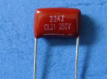
C1: Step-down capacitor, using a large capacitive reactance to limit the total circuit current. Commonly used polyester capacitor (CL21), polypropylene capacitor (CBB21), safety capacitor (X2), the capacity depends on the load demand, the larger the capacity of this capacitor, the more unsafe the circuit, in the design of this circuit, if the 220VAC power supply in the case of more than 2.5uF, If the capacity exceeds 4uF in the case of 110VAC power supply, other circuits should be considered because of the abandonment of resistance and capacitance reduction. Here, a 0.56uF safety capacitor (X2) is selected to provide 19mA current.
R2: discharge resistor. It provides a discharge circuit for capacitor C1 after the power plug is powered off. This prevents the residual voltage on the C1 capacitor and the grid voltage from superimposing on subsequent devices when the power plug is quickly inserted and removed or the plug is in poor contact. Generally, the time for C1 voltage attenuation to 37% after power failure should be less than 1 second, because T=RC*Ln[(V0-V1)/(Vt-V1)], so T=RC, R=t/C, R<1/C. Three 390K 0805 patch resistors are used here (sharing voltage and power).
R1: current limiting resistor, this resistor is mainly to prevent the rectifier diode from being damaged by the high voltage shock caused by the first power-on and the rapid insertion and removal of the power plug or poor plug contact. Capacitor C2 in the first power-on if just hit the peak, because C2 in the instant of power is short circuit state (first-order zero state response), at this time AC power directly added to R1 and the rectifier tube, R1 has 220VAC*1.414=311VDC instant DC voltage, if C1 charge is not released when powered on, this voltage may be higher. Therefore, R1 should choose a resistance with strong current impact and high voltage resistance, R1 resistance can not be too small, nor too large, the resistance is too small, the impact current is too large, and the entire circuit power consumption is increased. The peak current of the rectifier diode is generally large, such as the peak current of the 1N400X series is 50A, so the R1 resistance is generally between 10-50Ω.
DZ1: Voltage regulator diode, selected 1N4733, voltage regulator Vz is 5.1V. The maximum voltage regulating current Iz of DZ1 must be greater than the maximum charge and discharge current of the capacitor C1.
R5: Form RC filter with capacitor E1 and C2 to reduce ripple.
D1: Rectifier diode, half wave rectifier function, select 1N4007.
D2: Rectifier diode, half wave rectifier, selected 1N4007.
E1: The electrolytic capacitor filters the voltage after voltage regulation, and provides power to the load during half a cycle of power shutdown. Before the second half cycle of the power supply comes, the E1 must ensure that the voltage provided for the load cannot decay too much, and the 1000uF25V model is selected here. T=RC*Ln[(V0-V1)/(VT-v1)]=10mS, so the attenuated voltage Vt=4.8V.
C2: Chip capacitor, filter action, select 0.1uF.
R6: discharge resistance, after power off to provide E1 discharge circuit, generally 5~10K.
R7: equivalent load.
Pictures of the main components
Blow the fuse once
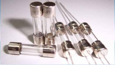
Self-restoring fuse
varistor
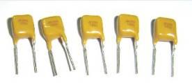
Metallized Polyester Film Capacitor (CL21)
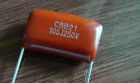
Metallized Polypropylene Capacitor (CBB21)
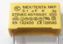
X2 Safety Capacitor (CBB62/MKP)
3, the application of resistance and capacitance pressure reduction
Because of its small size and low cost, it is suitable for low power and low current loads. Common applications are energy meters, low-power LED lamp drivers, small household appliances and temperature controllers.

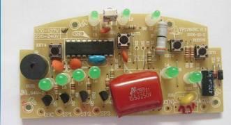
LED light driver

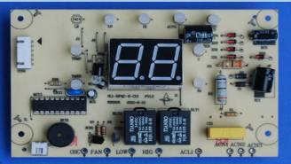
Fan controller
Coffee machine
免责声明: 本文章转自其它平台,并不代表本站观点及立场。若有侵权或异议,请联系我们删除。谢谢! Disclaimer: This article is reproduced from other platforms and does not represent the views or positions of this website. If there is any infringement or objection, please contact us to delete it. thank you! |

WeChat Official Account

WeChat Service
 Email
Email QQ
QQ 13823761625
