In this article, Texas Instruments will discuss the growing focus on 48V low-voltage rail systems in electric and hybrid vehicles and how engineers can leverage them to achieve new features while shrinking harness sizes and reducing costs.
introduction
In recent conversations with automakers, the 48V low-voltage rail has been mentioned frequently. But why now? 48V systems are not new. For years, it has been helping to improve the efficiency and performance of mild hybrid electric vehicles (MHEVs).
48V systems are again receiving attention, possibly related to the growing popularity of battery electric vehicles (BEVs) and hybrid electric vehicles (HEVs). Electric or hybrid vehicles that generate 48V voltage from a high-voltage battery can realize an important advantage of 48V systems: the addition of 48V low-voltage rails can reduce the specifications of the vehicle's power supply harness and reduce the load current requirements of downstream semiconductor components such as power switches and motor drivers. As a result, 48V systems can deliver more power than 12V systems, providing an opportunity to add features such as artificial intelligence or mini refrigerators.
BEV original equipment Manufacturers (Oems) are looking for ways to optimize the cost, weight, and range of BEVs. From an electrical point of view, reducing wiring harnesses through regional architectures, or using 48V low-voltage rails for power distribution, will make it possible to solve these three problems. In the early 20th century, the automotive industry used 6V voltage rails for power supply before the power demands of electrical/electronic (E/E) systems forced the market to move to 12V. Today, feature-rich vehicles are approaching the limits of the 12V voltage rail. Moving from 12V to 48V will present challenges, but it will also present opportunities for Oems with 48V low-voltage rails.
Application of 48V system in MHEV and BEV
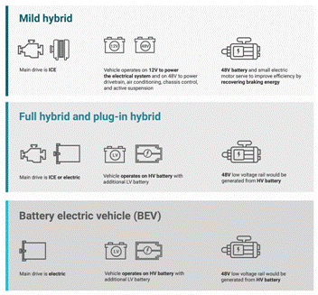
In the late 1990s, there was a push for 42V E/E systems. However, due to the lack of high-efficiency motors, Oems abandoned this approach and the market shifted to MHEVs using high-voltage starter generators. So while MHEVs are the "first" 48V systems, they only use 48V batteries and small motors to assist ICE to reduce fuel consumption and increase efficiency.
In MHEV, the primary low-voltage rail for the E/E system is still 12V, requiring a large bi-directional converter between the 48V and 12V voltage rails, which significantly increases the cost burden. In contrast, full hybrid vehicles (HEVs), plug-in hybrid electric vehicles (PHEVs), and BEVs can use high-voltage batteries to create 48V low-voltage rails that power the entire E/E system.
Due to the limited models and platforms, future BEV platforms have become the main target for Oems to deploy 48V automotive systems. The transition to electric vehicles has also increased investment in HEVs and PHEVs. Figure 1 Outlines the differences between the different vehicle types.
Reduced harness
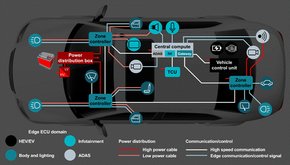
The first major attempt to reduce wiring harnesses was the introduction of a regional architecture, as shown in Figure 2, which optimizes vehicle wiring by grouping power distribution, communications, and load drivers based on location rather than function. The regional architecture reduces vehicle wiring by using smart semiconductor fuses instead of traditional blown fuses for power distribution and acts as a communication gateway from the central computer to sensors, actuators and electronic control units (ECUs).
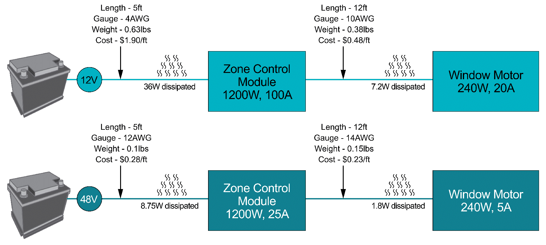
While the main benefit of moving to 48V is reduced cable specifications, cable cost is not the only factor. Today, installing coarse specification cables such as American Cable Specification (AWG) No. 4 on vehicles requires a lot of labor. By reducing cable specifications in 48V systems, it will be possible to install wiring harnesses using automated manufacturing processes, resulting in significant cost reductions.
48V architecture
When optimizing harnesses for 48V architectures, Oems need to evaluate different architectures. Figures 4 to 6 show three options for implementing a 48V low-voltage rail: 48V main and 12V local distribution, 48V and 12V distribution, or just 12V distribution and 48V high-current load.
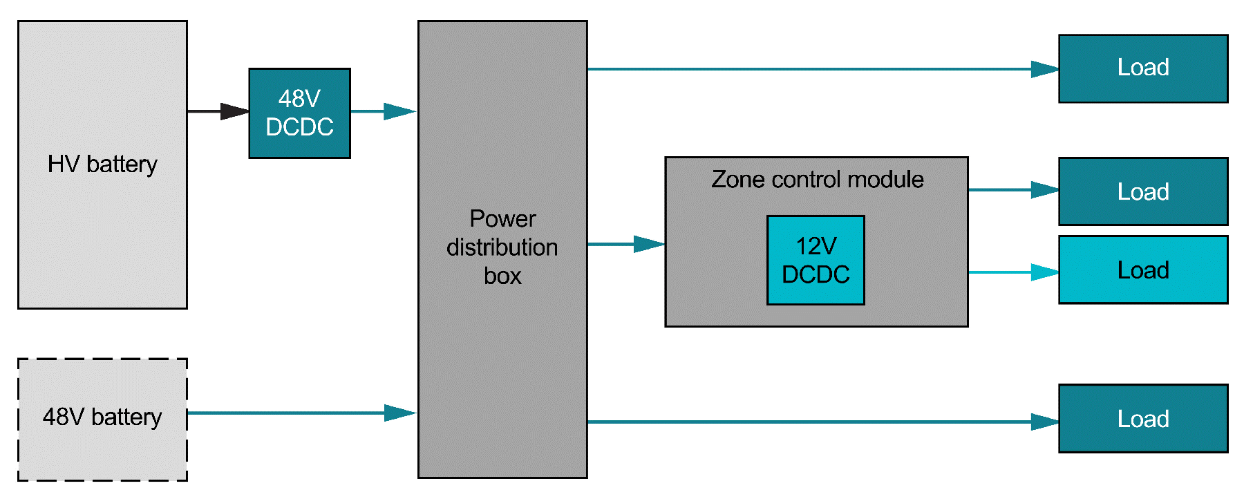
Figure 4:48 V architecture (48V main distribution, 12V local distribution)
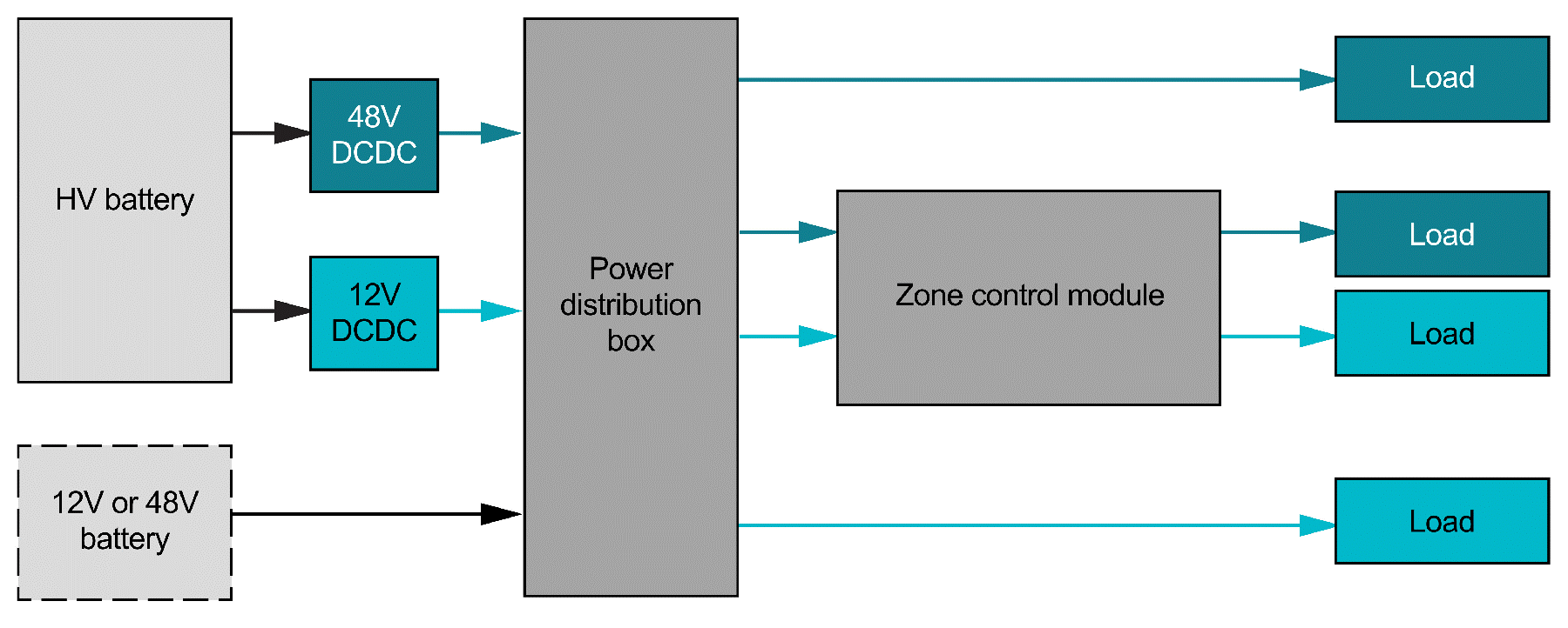
Figure 5:48V and 12V power distribution - ZCM 48V and 12V
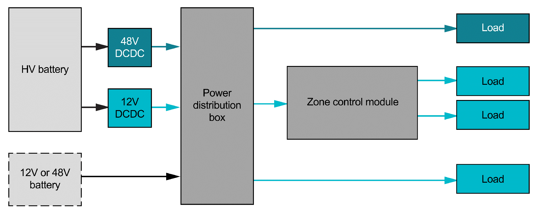
A more radical design change is to adopt the 48V distribution architecture directly and generate 12V rail locally as needed. 48V distribution with local 12V voltage is the best architecture to realize all the benefits of switching to 48V, as it minimizes harness size and cost.
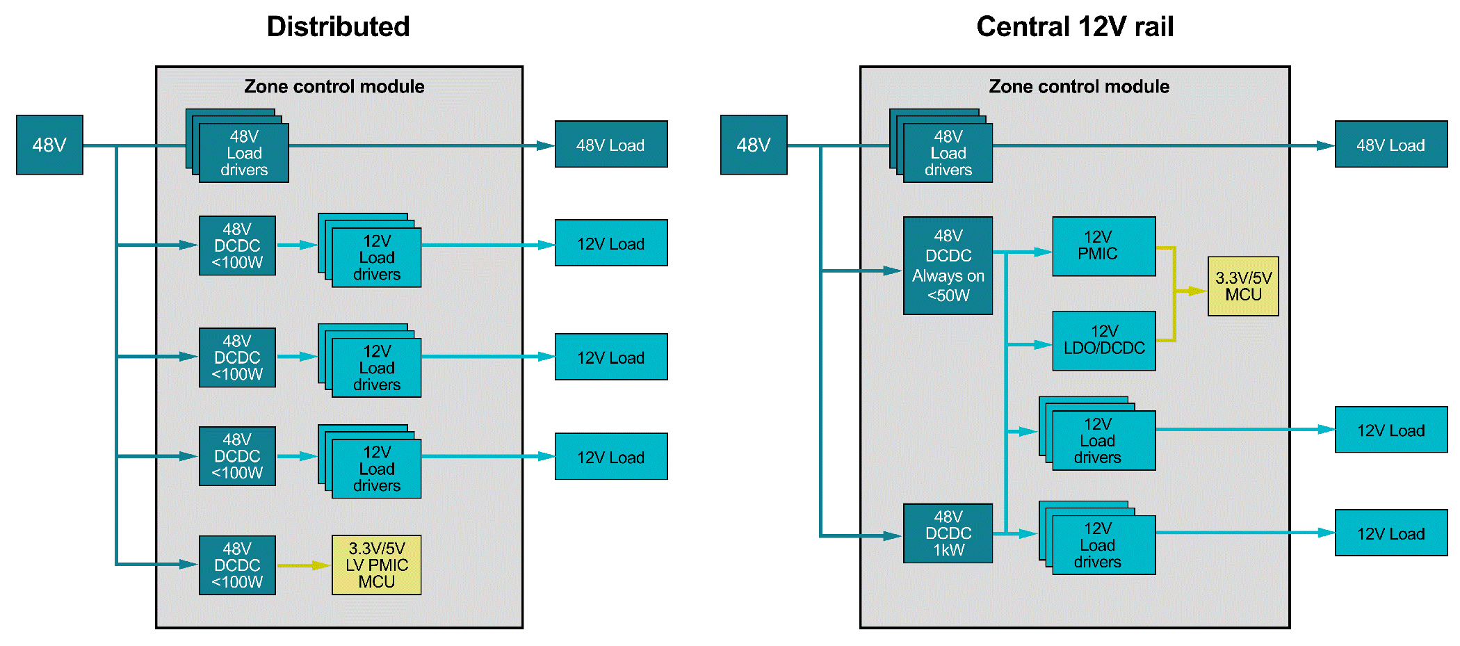
In 48V distribution with local 12V voltage, there are a number of different options that can be used to form a local 12V voltage rail on the ECU, or used to select a completely different voltage (25V, 16V, 5V, 3.3V). Figure 7 provides two possible power architectures for a 48V system: distributed 12V and centralized 12V.
Design challenges for 48V systems
Design challenges with 48V low-voltage rails include transient voltage, creepage distance and electrical gap requirements, electromagnetic compatibility (EMC) standards, and integrated circuit (IC) costs.
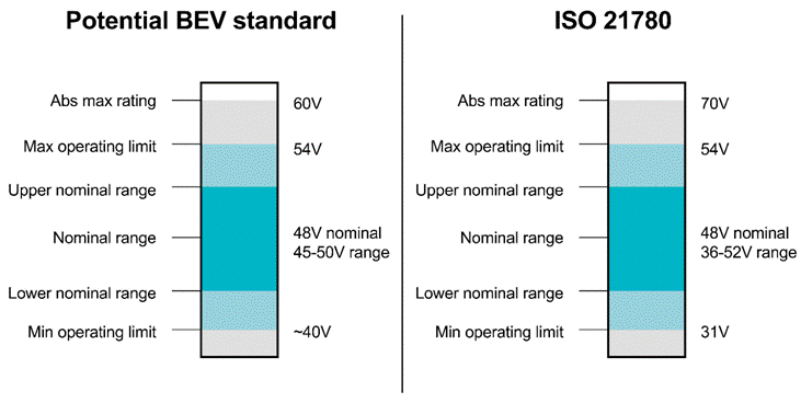
Transient voltage is a major topic of discussion in 48V systems. Today, 12V systems are well known, and standards such as ISO 16750-2 specify voltage transients under the most demanding conditions, such as load drops. For 48V systems, the current standards (ISO 21780 and Liefervorschriften [LV] 148) are specifically developed for MHEVs that require overvoltage points up to 70V. However, if switching transients or component margins are taken into account, the component voltage rating will be much higher than 70V.
While MHEV standards can be used as a starting point, they are not necessarily applicable for electric or hybrid power systems that do not use a high-power starter generator system, but instead generate 48V voltage from a high-voltage battery. Specific standards for BEV 48V low-voltage networks are still being developed, but Oems may begin to develop their own standards to keep line transients below 70V. Figure 8 compares the potential BEV standard to the existing ISO 21780 standard.
Creepage distance and electrical clearance requirements refer to the measurement of the shortest distance between all conductive components on a PCB according to industry standards. When the voltage between two points exceeds the breakdown voltage, an arc is generated, and the creepage distance and electrical gap are key design parameters to prevent arcing. There are several different creepage distance and electrical clearance standards (International Electrotechnical Commission 60664-1 and Printed Circuit Association 2221A), and Oems may even have their own internal guidelines. Upgrading from 12V to 48V will increase creepage distance and electrical clearance requirements, directly affecting IC packaging, PCB layout, and wiring harness connectors.
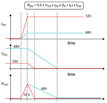
A more subtle effect of a 48V system is that while it helps to reduce conduction losses, switching losses increase. This is important in EMC testing for switching power converters such as DC/DC converters and motor drivers. Increasing the voltage (VDS) from 12V to 48V can reduce the current (IDS). However, if the conversion rate (tR + tF) in a 48V system is still the same as in a 12V system, then the power switching loss (PSW) becomes four times greater.
While there are many more factors that affect switching loss, Figure 9 illustrates how the conversion rate affects switching loss in a 48V system.
Conclusion
The 48V system can reduce the weight and size of the wire harness, which saves the actual copper cost of the wire and the manufacturing cost. Whether at the IC level or the system level, the adoption of 48V comes with a number of advantages and challenges that will impact costs in some way. Oems will decide when and how to integrate 48V systems to maximize benefits and reduce costs. Recent vehicle innovations prove that the market and semiconductor suppliers are ready for 48V systems.
免责声明: 本文章转自其它平台,并不代表本站观点及立场。若有侵权或异议,请联系我们删除。谢谢! Disclaimer: This article is reproduced from other platforms and does not represent the views or positions of this website. If there is any infringement or objection, please contact us to delete it. thank you! |


