
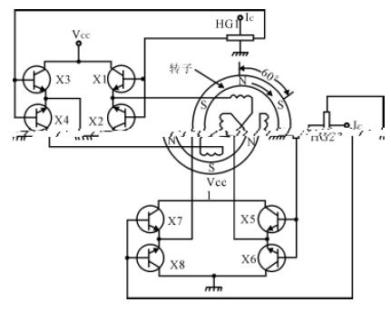
Motor drive circuit with Hall element
The DC brushless motor uses a permanent magnet rotor to place the required number of Hall devices in the appropriate position of the stator, and their output is connected to the supply circuit of the corresponding stator winding. When the rotor passes near the Hall device, the magnetic field of the permanent magnet rotor causes the energized Hall device to output a voltage to turn on the stator winding power supply circuit, supply power to the corresponding stator winding, generate a magnetic field with the same polarity as the rotor magnetic field, and repulse the rotor to continue rotating. To the next position, the Hall device in the previous position stops working, and the Hall device in the next position is switched on, so that the next winding is energized, and a repulsion field is generated to make the rotor continue to rotate. This cycle keeps the motor working. The working principle is shown in Figure 1.
A Hall device in a brushless motor can use either a Hall component or a Hall switching circuit. When using Hall components, it is generally necessary to connect an external amplifier circuit, as shown in Figure 2. Using Hall switching circuit, the motor winding can be directly driven, so that the line is greatly simplified, as shown in Figure 3.
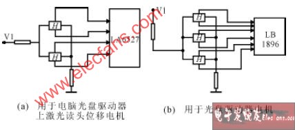
图2采用霍尔元件的电机驱动电路 (图中的H 为霍尔元件)
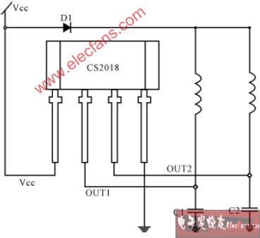
Figure 3. Circuit diagram of direct motor drive with CS2018 Hall switch locking circuit (the coil in the figure is the stator winding of the motor)
免责声明: 本文章转自其它平台,并不代表本站观点及立场。若有侵权或异议,请联系我们删除。谢谢! Disclaimer: This article is reproduced from other platforms and does not represent the views or positions of this website. If there is any infringement or objection, please contact us to delete it. thank you! |

WeChat Official Account

WeChat Service
 Email
Email QQ
QQ 13823761625
