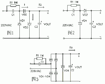
The basic circuit of the capacitor step-down type simple power supply is shown in Figure 1. C1 is a step-down capacitor, D2 is a half-wave rectifier diode, D1 provides a discharge circuit to C1 during the negative half cycle of the mains, and D3 is a voltage regulator diode R1 is the charge drain resistance of C1 after the power is turned off. The circuit shown in Figure 2 is often used in practical applications. When a large current needs to be supplied to the load, the bridge rectifier circuit shown in Figure 3 can be used. The unregulated DC voltage after rectification is generally higher than 30 volts, and will fluctuate greatly with the change of load current, this is because the internal resistance of this kind of power supply is very large, so it is not suitable for high-current power supply applications.
1. When designing the circuit, the exact value of the load current should be determined first, and then the capacity of the step-down capacitor should be selected by reference to the example. Because the current Io provided to the load through the buck capacitor C1 is actually the charge and discharge current Ic flowing through C1. The larger the capacity of C1 and the smaller the capacitive reactance Xc, the larger the charging and discharging current flowing through C1. When the load current Io is less than the charge and discharge current of C1, the excess current will flow through the regulator. If the maximum allowable current Idmax of the regulator is less than Ic-Io, the regulator may burn out.
2. In order to ensure the reliable operation of C1, its voltage should be more than twice the power supply voltage.
3. The selection of bleed resistor R1 must ensure that the charge on C1 is discharged within the required time.
3. Design examples
In Figure 2, C1 is known to be 0.33μF, AC input is 220V/50Hz, and the maximum current that the circuit can supply the load is calculated.
The capacitive reactance Xc of C1 in the circuit is:
Xc=1 /(2 πf C)= 1/(2*3.14*50*0.33*10-6)= 9.65K
The charging current (Ic) flowing through capacitor C1 is:
Ic = U / Xc = 220 / 9.65 = 22mA。
Generally, the relationship between the capacity C of the buck capacitor C1 and the load current Io can be approximated as: C= 14.5I, where the capacity unit of C is μF and the unit of Io is A.
Capacitor step-down power supply is a non-isolated power supply, and special attention should be paid to isolation in application to prevent electric shock.
免责声明: 本文章转自其它平台,并不代表本站观点及立场。若有侵权或异议,请联系我们删除。谢谢! Disclaimer: This article is reproduced from other platforms and does not represent the views or positions of this website. If there is any infringement or objection, please contact us to delete it. thank you! |


