
Is it possible to double the output current by parallel operation?
Every once in a while, I see similar questions on the E2E forums. Although we would say yes, it's enough to give us a little chills. This is possible, but be very careful. Now, let's see where the key points are. Do not use the circuit on the left in the image below: directly paralleling the input and output of two op-amps can cause serious problems. Different offset voltages will cause the output voltages to adjust to each other. One op amp may be used as a current source to inject current into another op amp, and may therefore lose all current drive capability.
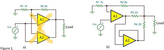
Figure 1b has been improved. The op amp A1 acts as the primary output, and the op amp A2 acts as the secondary output, following the main output voltage. Even though A2's output will be slightly different from A1's, R3 and R4 will force the system to distribute the output current properly. The feedback point is drawn from the intersection of R3 and R4 on the load side to ensure the correct pressure drop. The I∙R voltage drop of these resistors will cause some loss in the output voltage swing, so you will want to reduce the resistance value of these resistors. At the same time, the offset voltage of A2 will generate an additional static current Vos/(R3+R4). Choosing a resistor here requires a trade-off.
Handle high-speed signals with caution. The system expects A2 to follow the output of A1 exactly. If the signal is too fast, A2's phase shift will cause a difference in the output voltage, which will lose a portion of the output current. It is very important to avoid the output swinging too fast. If possible, add an R-C filter to the input to make the A1 output of the rapidly changing signal slower than the voltage swing rate, because the dynamic output performance of the two opamps may not match so well under rapid changes.
Do not use older generation opamps, which have an output reversal (phase reversal) feature. If the output of A1 exceeds the input common-mode voltage range of A2, and its output voltage is reversed, the result will be very bad.
In short, thoroughly check your circuitry. SPICE simulations can tell whether the basic circuit will work, but the operational amplifier model cannot accurately predict the occurrence of rare problems in the circuit. Set up a test board and double-check all signals and conditions. If your op amp has multiple resources, you should also consider the performance differences of devices from different manufacturers.
You'd think I'd be very careful when using parallel transport. Yes, simultaneous transport is feasible, but the design needs to be careful. I recommend the simpler way, which is to choose an op amp with a high current output. Here are some alternative opamps:
•TLV4111 300mA, 6V. CMOS Op Amp.
•BUF634 G=1 buffer, 200mA, 36V. Used inside the feedback loop of standard op amps.
•OPA547 500mA, 60V Op Amp. Adjustable current limit.
•OPA564 1.5A, 24V Op Amp, 17MHz GBW.
•OPA548 5A, 60V Op Amp. Adjustable current limit.
免责声明: 本文章转自其它平台,并不代表本站观点及立场。若有侵权或异议,请联系我们删除。谢谢! Disclaimer: This article is reproduced from other platforms and does not represent the views or positions of this website. If there is any infringement or objection, please contact us to delete it. thank you! |

WeChat Official Account

WeChat Service
 Email
Email QQ
QQ 13823761625
