
As energy conservation has become a global focus, the energy efficiency of motor design has also become a concern. As governments have introduced various regulations to improve energy efficiency, motor drive circuits have become increasingly complex in order to meet the energy efficiency challenge. This article discusses product and industry trends in motor drive circuits and provides solutions that help designers reduce energy consumption, improve reliability, reduce component counts, and become environmentally friendly.
Types of motors in the industrial field
In the past 100 years, electrical products mainly use induction motors, even frequency conversion driven appliances, but also the use of induction motors. Now some new electrical appliances are starting to use more efficient, more compact and lighter motors. These new motors can be divided into two main categories, brushless DC motors and switched reluctance motors.
Many common household appliances use brushless DC motors with variable frequency drives. These efficient general-purpose motors have a high torque density. As energy prices soar, the industry has renewed interest in brushless DC motors. But the cost, as well as the overall complexity of the drive design, has been a barrier to widespread adoption.
Switched reluctance motors are mostly used in appliances such as vacuum cleaners and hand-held power tools that do not pay attention to motor noise and torque fluctuations. Switched reluctance motors are characterized by large torque and high speed, but the price is very competitive.
Both brushless DC motors and switched reluctance motors use a microcontroller or DSP to adjust the waveform, and then use a power switch (power MOSFET or IGBT) to amplify the adjusted waveform.
Driving circuit
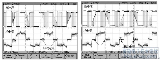
Variable frequency drive circuits can be designed in many different ways. In a typical three-phase motor, the most popular low-frequency drive scheme is the trapezoidal wave drive circuit, as shown in Figure 1. Figure 2 shows the actual test waveform of the trapezoidal wave drive circuit。
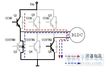
Figure 1: The most popular low frequency drive scheme - trapezoidal wave drive circuit.
There are two popular types of permanent magnet three-phase synchronous motors, namely sinusoidal permanent magnet synchronous motors and trapezoidal wave brushless DC motors. Sine permanent magnet synchronous motor and trapezoidal wave brushless DC motor (electrical performance) is very similar, their difference is mainly reflected in the following two aspects: (1) the motor structure or back electromotive force (BEMF) waveform is different, one is the induction voltage sine permanent magnet synchronous motor, the other is trapezoidal wave brushless DC motor; (2) The waveform of the control voltage is different, one uses three-phase sine (all three phases have current flowing at the same time), and one uses rectangular six-step commutation.
Among new drives, sinusoidal permanent magnet synchronous motors are becoming more and more popular and are beginning to replace brushed and brushless DC motors, general-purpose (AC asynchronous) motors and other motors (such as household variable frequency air conditioners, industrial sewing machines, etc.) in many applications. The reason is that it is more reliable (brushless), more efficient, less noisy, and has a very high voltage utilization and low frequency torque in terms of electrical control. Figure 3 and Figure 4 respectively show the system block diagram and experimental waveform of a position-free vector controller based on magnetic field oriented control (FOC).
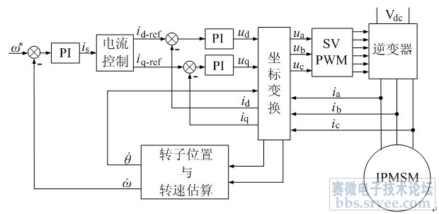
Figure 3: Block diagram of vector control system of built-in Permanent magnet synchronous motor (IPMSM).

Innovative solution: Smart power module
An intelligent power module (SPM) is a power interface between a microcontroller or DSP and a motor that reduces the size of the motor and simplifies the design. The advantages of this module over discrete solutions are lower parasitic inductance and higher reliability, because all power devices in the module use the same batch of chips and have consistent test performance. This smart power module can interface directly with the low-voltage TTL or CMOS output of the microcontroller and has a protection circuit. The module has a built-in thermistor to monitor junction temperature, a logic protection circuit to prevent the upper and lower bridge arms from passing through, dead time control, and a drive waveform shaping circuit to minimize EMI, etc. In the module, each driver IC can be optimized to perform the switching action of the power device with minimal EMI and drive losses. Three-phase drive modules will continue to be widely used in electrical products. Figure 5 shows a typical application circuit for motor control using SPM.
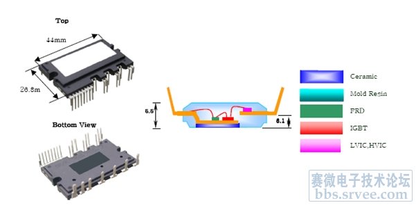
Figure 6 shows the appearance and internal structure of the Motion-SPM smart power module in the Mini-DIP package. Motion-SPM is an ultra-compact power module, which integrates the power element, upper and lower bridge arm gate driver and protection circuit in a dual in-line mode-shifting package for AC 100~220V low power motor drive frequency conversion control.
The smart power module is designed for maximum design flexibility and can be used in different output voltages and power ranges.
High voltage (600V) bridge drive technology
The (600V) high-voltage bridge drive technology enables small, low-cost modules to drive changes in motor drive circuits. Modern high voltage bridge gate driver circuits are carefully designed to reduce the parasitic drain capacitance inherent in the high voltage IC chip process. In this way, the drive circuit is robust enough to withstand negative voltages exceeding -9V. The positive and negative peak voltages on the supply voltage do not cause latching and gate control failures in the driver circuit, which is a major change in the grid drive circuit in the last 10 years. The matching transmission delay is less than 50ns, so that the switching frequency can reach 100kHz or 150kHz. The addition of a common-mode dV/dt noise cancellation circuit within the IC also helps to reduce the possibility of false conduction, which also helps to make the power circuit more robust, while also making the circuit more compact by eliminating additional filtering components. Modern ics, such as the FAN7382 and FAN7384, have lower static currents and lower operating temperatures, so they are more reliable. The reduction in the system power board space and cost reflects a major advantage of modular technology, which eliminates the four power supplies common in the previous generation motor drive circuit and the photoelectric coupling circuit between the microcontroller PCB and the power switch PCB.
Comparison between NPT type and PT type IGBT
For 20 years, IGBTs have been used as power switching devices for motor drives. Igbts are designed to minimize losses for a specific switching frequency. For the motor drive industry, this means a range of IGBTs ranging from 5kHz switches for some consumer electronics motors to 20kHz switches for many industrial motors, and even higher frequency switches for applications other than motor drives.
Improvements in IGBT technology, such as on-voltage and off power consumption per switching cycle, have also further improved reliability and reduced module costs. In the last five years, conventional IGBTs have improved dramatically in terms of functionality, and new non-punch-through (NPT) IGBTs have also been applied on a large scale.
NPT IGBTs look similar to traditional through-through (PT) IGBTs, but the manufacturing method is very different. Unlike MOSFETs or traditional IGBTs, NPT IGBTs use P-type zones and backside metal zones in silicon wafer fabrication.
NPT IGBTs often have a lower turn-on voltage (VCE(SAT)) than conventional IGBTs, or a slower turn-on speed, but they are generally more robust and can withstand short circuits or overcurrents for longer. This makes it popular in motor control applications. In addition, if you look at the switching waveforms of these two IGBTs, you will find that the NPT IGBT produces much lower EMI than the PT IGBT. The lower edge of the NPT IGBT switching pulse is basically a simple slope, while the traditional IGBT is a large area of dI/dt, followed by a long tail with a slow current drop rate, and the loss of the device is high. In the high dI/dt area, the EMI generated by the traditional IGBT is large, which generally affects the drive circuit, and it is often necessary to isolate the power switch from the drive circuit. Another advantage of NPT IGBTs is that they can form a positive temperature coefficient relationship with VCE(SAT), which is very useful for IGBT parallel applications.
Fairchild's low-on-impedance 600V SuperFET MOSFET family is specially packaged in the DPAK(TO-252) package TO meet the requirements of the latest ultra-slim and thin devices for motion control applications. In order to minimize switching and on-off losses to meet the system efficiency requirements of some high-switching frequency motor control designs, the on-impedance of these products is reduced to one-third (0.6 to 1.2 ohms) of traditional planar MOSFETs. In addition, these products can withstand fast voltage transients (dv/dt) and current transients (di/dt), allowing the system to operate reliably at high switching frequencies.
Summary of this article
Recently, the demand for energy-efficient household appliances has been strong. In household appliances, the electricity consumption of a refrigerator will account for more than 10% of the entire household electricity consumption. Since refrigerator compressors mainly work at low speeds, improving motor drive efficiency at low speeds has great energy saving potential. To achieve this, Fairchild has developed solutions for brushless DC motors based on sinusoidal converters for refrigerators and air conditioners. The new motor drive technology targets high - and low-speed compressor motor applications to further improve overall drive efficiency.
With an estimated 65% of industrial electricity consumed by electric motors, it is no wonder that major companies in the industry are increasingly focusing on energy conservation as the key to improving profits and competitiveness. One answer is energy savings, especially in motors. There are two main methods, that is, the use of variable frequency speed control drive scheme to efficiently control the working speed of the motor, real-time feedback of the motor operating state and other parameters, and improve the efficiency and performance of the motor itself, because variable speed drive in improving performance, but also energy saving and improve productivity.
免责声明: 本文章转自其它平台,并不代表本站观点及立场。若有侵权或异议,请联系我们删除。谢谢! Disclaimer: This article is reproduced from other platforms and does not represent the views or positions of this website. If there is any infringement or objection, please contact us to delete it. thank you! |

WeChat Official Account

WeChat Service
 Email
Email QQ
QQ 13823761625
